ACM-IP2 ANALOGUE SUBSYSTEMS MODULE
User Manual
page 22/28
armtel.com
© Armtel
info@armtel.com
ENG
APPENDIX A
(REFERENCE)
ACM-IP2 CONNECTION DIAGRAMS
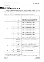
The pin numbers and the designation of the circuits for external connection is given in
.1. The numbering of contacts and the designation of circuits on the module are in
accordance with Figure 2.
Table A.1 - The pin numbers and the designation of the circuits for external connection
Sockets
Pin No
Circuit
Designation
Х21
2
-48V
Power input from the external power supply or
power output for power supply via
РоЕ
line
3
+0V
Х11
1
Lin1
Control line 1, discrete input / output
2
Lin2
Control line 2, discrete input / output
3
Lin3
Control line 3, discrete input / output
4
Lin4
Control line 4, discrete input / output
5
Lin5
Control line 5, discrete input / output
6
Lin6
Control line 6, discrete input / output
7
Lin7
Control line 7, discrete input / output
8
Lin8
Control line 8, discrete input / output
X3
1
+V
External control of receiving/transmission
2
CP2
Middle point of the LF line transformer
3
ADC_CH2.2
Analogue communication line 1 (symmetrical
a/b line with transformer isolation)
4
ADC_CH1.2
Х4
*
1
+V
External control of receiving/transmission
2
CP1
Middle point of the LF line transformer
3
ADC_CH2.1
Analogue communication line 2
(symmetrical
a/
b
line with transformer isolation
)
4
ADC_CH1.1
Х8
**
5,6
SPK CH1
Outputs of integrated amplifier
7,8
SPK CH2
Х22
1,2
-48 V
Negative potential of the control line
* - Output from
Х
3 is used, output from
Х
4 is stand-by;
** - Transmission of audio information is simultaneously conducted on both channels of the amplifier


