ARNAV Systems, Inc.
11
Document No. 570-8050B
27 November 2002
Wiring the RCOM-100, VC28, PTA-12:
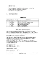
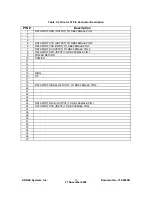
Table 3-3 is the pin definition for the circular 37-pin connector. The RCOM-100 has been
designed to work with either a 28VDC aircraft or a 14VDC aircraft. TIP and RING are for EIA/TIA-
464B compatible telephone equipment. The DATA PORT shows how it should be wired up to a
DB-9 female connector, which should then plug into a DTE device.
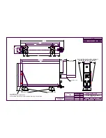
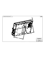
Refer to wire diagram ENG-5024.
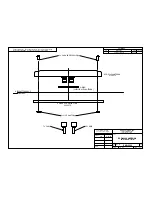
Refer to wire routing on drawing ENG-5021. Route wires from the back of the aircraft at the
RCOM-100 along the right side of the aircraft and below the doorframe to the area behind the
control panel where the wires connect to the audio panel and PTA-12. Assured that the cables
are secured and avoid routing near any control cables or moving surfaces.
Connect the aircraft equipment per wire diagram ENG-5024. Add a 5-amp circuit breaker for the
RCOM-100 and a 1-amp circuit breaker for the PTA-12.
The telephone audio can come from either the PTA-12 dialer as a headset microphone interface
(see NAT PTA-12 Install manual – Appendix B), or it can interface with an existing audio panel.
This install drawing shows connection to an audio panel with a Tip/Ring telephone interface. For
audio panels without the Tip/Ring telephone input, refer to the NAT PTA-12 install manual for
instructions on connecting the PTA-12 audio signals into an audio panel.
Summary of Contents for RCOM-100
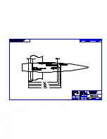
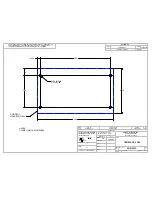
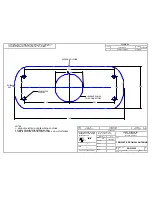
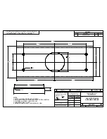
Page 9: ...ARNAV Systems Inc 8 Document No 570 8050B 27 November 2002 Antenna Mount Outside View ...
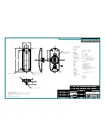
Page 17: ...ARNAV Systems Inc 16 Document No 570 8050B 27 November 2002 Appendix A Drawings ...
Page 21: ......
Page 27: ...ARNAV Systems Inc 17 Document No 570 8050B 27 November 2002 Appendix B PTA 12 Install Manual ...
Page 28: ......
Page 29: ......
Page 30: ......
Page 31: ......
Page 32: ......
Page 33: ......
Page 34: ......
Page 35: ......
Page 36: ......
Page 37: ......
Page 38: ......
Page 39: ......
Page 40: ......
Page 41: ......
Page 42: ......


