ARNAV Systems, Inc.
3
Document No. 570-8050B
27 November 2002
1.
INTRODUCTION
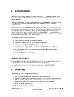
The RCOM-100 is a Globalstar satellite telephone for aviation. It is housed in an ARINC 600 2
MCU enclosure. The RCOM-100 is designed to provide voice and data communication in an
avionics application.
The voice connection is established through a standard TIP/RING interface. The RCOM-100 can
be connected to any standard telephone handset that complies with EIA/TIA-464B and
TIA/EIA/IS-470-B.
The data connection is through the RCOM-100 data port. The data port supports two types of
data services: asynchronous data, and packet data. Asynchronous data provides the capability
of establishing a connection between a device connected to the data port, and any Hayes
compatible modem connected to the Public Switch Telephone Network. For packet data the
device connected to the data port must be able to support a PPP session over TCP/IP. This is the
typical standard used by computers for dial-up services.
The installation to the RCOM-100 consists of:
•
Locating and mounting the transmit/receive antenna
•
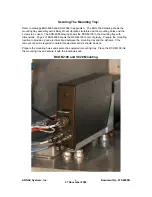
Installation of the mounting tray for the ARINC 600 2MCU box
•
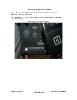
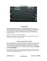
Locating and mounting the NAT PTA-12 Dialer
•
Locating and mounting the VC28 DC-to-DC converter (14 to 28 volts for PTA-12_
•
Wiring the RCOM-100 37 pin circular connector for power, tip/ring, and the data
connection port.
•
Wiring the PTA-12 to the Audio Panel.
Installation Requirements:
When installing the ARNAV RCOM-100 the installer must have a working knowledge of aircraft
electronics installation, and be a holder of a FAA Repairman’s Certificate.
All installations should meet the requirements of FAA advisory circular
AC43.13-1B
.
2.
OVERVIEW
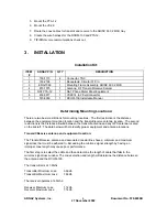
The main tasks for this installation are listed below:
1. Check the shipped installation kit components against this manual.
2. Determine the approximate location of the RCOM-100, the transmit/receive antenna, the
PTA-12, and the VC28. Factors considered for locations are minimum and maximum
antenna coax lengths, and minimum GPS and transmit antenna separation.
3. Mount the ARINC 600 2 MCU tray.
4. Mount the transmit/receive antenna.
Summary of Contents for RCOM-100
Page 9: ...ARNAV Systems Inc 8 Document No 570 8050B 27 November 2002 Antenna Mount Outside View ...
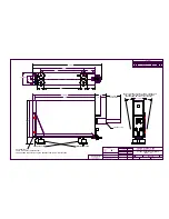
Page 17: ...ARNAV Systems Inc 16 Document No 570 8050B 27 November 2002 Appendix A Drawings ...
Page 21: ......
Page 27: ...ARNAV Systems Inc 17 Document No 570 8050B 27 November 2002 Appendix B PTA 12 Install Manual ...
Page 28: ......
Page 29: ......
Page 30: ......
Page 31: ......
Page 32: ......
Page 33: ......
Page 34: ......
Page 35: ......
Page 36: ......
Page 37: ......
Page 38: ......
Page 39: ......
Page 40: ......
Page 41: ......
Page 42: ......


