ARNAV Systems, Inc.
4
Document No. 570-8050B
27 November 2002
5. Mount the PTA-12
6. Mount the VC28.
7. Route the coax cables for transmit and receive to the ARINC 600 2 MCU tray.
8. Create the wire harness for the RCOM-100 and PTA12.
9. TIP/RING voice communications check out.
3.
INSTALLATION
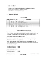
Installation Kit:
ITEM
#
ARNAV P/N
QTY
DESCRIPTION
1
150-1115
4
Connector, TNC
2
150-2168
1
Receptacle, Circular 37 Pin
3
ENG-7069
1
Mounting Frame Assembly, ARINC 600 2 MCU
4
870-1575
1
Antenna, RF Transmit/Receive Satcom
5
NAT PTA-12
1
NAT Phone Dialer Panel Equipment
6
453-0917
1
VC28 14 to 28 volt converter
7
570-8050
1
RCOM-100 Installation Manual
Determining Mounting Locations:
There are two basic restrictions for mounting locations. The first restriction is the distance
between the equipment mounting location and the transmit/receive antenna location. The second
restrictions is the distance allowed between the transmit antenna and any GPS antenna located
on the aircraft. The data below will help identify proper equipment and antenna locations.
Transmit/Receive antenna and equipment location:
The Transmit/Receive antenna and associated coaxial lines have a minimum and maximum
signal loss that must be adhered to. Exceeding the min/max signal strength by having an
improper coax length may cause poor performance.
The first step is to select the cable and then determine the length of cable that falls in the
min/max signal loss window. The coax selection and length will determine the distance between
the antenna and the RCOM-100.
The transmitter is at 1.6Ghz.
Transmitter Minimum Loss:
0.66db
Transmitter Maximum Loss:
1.66db
The receiver operates at 2.5Ghz.
Receiver Minimum Loss:
1.14db
Receiver Maximum Loss:
7.14db
Summary of Contents for RCOM-100
Page 9: ...ARNAV Systems Inc 8 Document No 570 8050B 27 November 2002 Antenna Mount Outside View ...
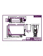
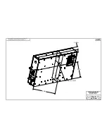
Page 17: ...ARNAV Systems Inc 16 Document No 570 8050B 27 November 2002 Appendix A Drawings ...
Page 21: ......
Page 27: ...ARNAV Systems Inc 17 Document No 570 8050B 27 November 2002 Appendix B PTA 12 Install Manual ...
Page 28: ......
Page 29: ......
Page 30: ......
Page 31: ......
Page 32: ......
Page 33: ......
Page 34: ......
Page 35: ......
Page 36: ......
Page 37: ......
Page 38: ......
Page 39: ......
Page 40: ......
Page 41: ......
Page 42: ......


