ARNAV Systems, Inc.
5
Document No. 570-8050B
27 November 2002
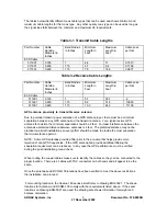
The tables below identify different coax cable types that can be used and shows minimum and
maximum cable lengths for that coax type. Any other quality coax type can be used as long as
the signal loss falls between the minimum and maximum db requirements.
Table 3-1 Transmit Cable Lengths
Part Number
Cable
Outside
Diameter in
Inches
Bend Radius
in Inches
Minimum
Length in
Feet
Maximum
Length in
Feet
Cable Loss
per foot
ECS Cable
311901
0.195
1
4.4
11
0.1513
311601
0.229
1.15
3.7
9.4
0.1768
311501
0.229
1.15
7.5
18.9
0.0877
Table 3-2 Receive Cable Lengths
Part Number
Cable
Outside
Diameter in
Inches
Bend Radius
in Inches
Minimum
Length in
Feet
Maximum
Length in
Feet
Cable Loss
per foot
ECS Cable
311901
0.195
1
5.7
35.7
.2
311601
0.229
1.15
8.2
51.5
.13850
311501
0.229
1.15
10.3
64.3
.11100
GPS antenna proximity to transmit/receive antenna:
Due to potential transmit power saturation of a GPS antenna input, there must be a minimum
separation between any GPS antenna and the transmit antenna. For a typical active GPS
antenna for aviation the minimum separation should be 2 feet. For least interference between the
antennas a preferred distance between antennas is 4 feet. The preferred distance may not be
practical on aircraft installations so every effort should be made to provide the most separation
that circumstances permit.
NOTE: Some GPS antennas provide a filter prior to the pre-amp that helps provide more
rejection of non-GPS frequencies. If the GPS antenna can provide additional filtering the
separation requirement can be reduced. In any case the GPS performance must be verified
during the post-installation ground check.
When routing the coaxial cables make sure to identify the cables so they can be connected to the
proper location. There are 2 cables with TNC connectors on both ends and all appear to be the
same.
Once the antennas and RCOM-100 locations have been verified to meet the above restrictions
the installation can proceed.
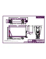
For mounting location in the Cessna 180 series aircraft refer to drawing ENG-5021. The shown
locations for Antenna, and RCOM-100 comply with the requirements listed above. If the exact
locations on drawing ENG-5021 are used, the drawing also shows information for weight and
balance calculation.
Summary of Contents for RCOM-100
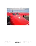
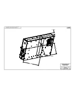
Page 9: ...ARNAV Systems Inc 8 Document No 570 8050B 27 November 2002 Antenna Mount Outside View ...
Page 17: ...ARNAV Systems Inc 16 Document No 570 8050B 27 November 2002 Appendix A Drawings ...
Page 21: ......
Page 27: ...ARNAV Systems Inc 17 Document No 570 8050B 27 November 2002 Appendix B PTA 12 Install Manual ...
Page 28: ......
Page 29: ......
Page 30: ......
Page 31: ......
Page 32: ......
Page 33: ......
Page 34: ......
Page 35: ......
Page 36: ......
Page 37: ......
Page 38: ......
Page 39: ......
Page 40: ......
Page 41: ......
Page 42: ......


