ARNAV Systems, Inc.
6
Document No. 570-8050B
27 November 2002
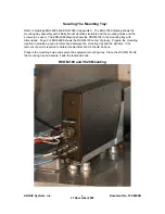
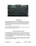
Securing The Mounting Tray:
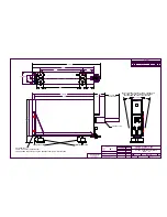
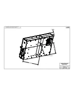
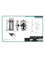
Refer to drawings ENG-4985 and ENG-7069 in appendix A. The ENG-7069 drawing shows the
mounting tray assembly with 4 Barry Mount vibrations isolators and the mounting holes and the
screws to be used. The ENG-4985 drawing shows the RCOM-100 in the mounting tray with
dimensions. Page 2 of ENG-4985 shows the RCOM-100 center of gravity. Prepare the mounting
location to provide a good electrical bond between the mounting tray and the airframe. If the
removal of paint is required to obtain this electrical bond it should be done.
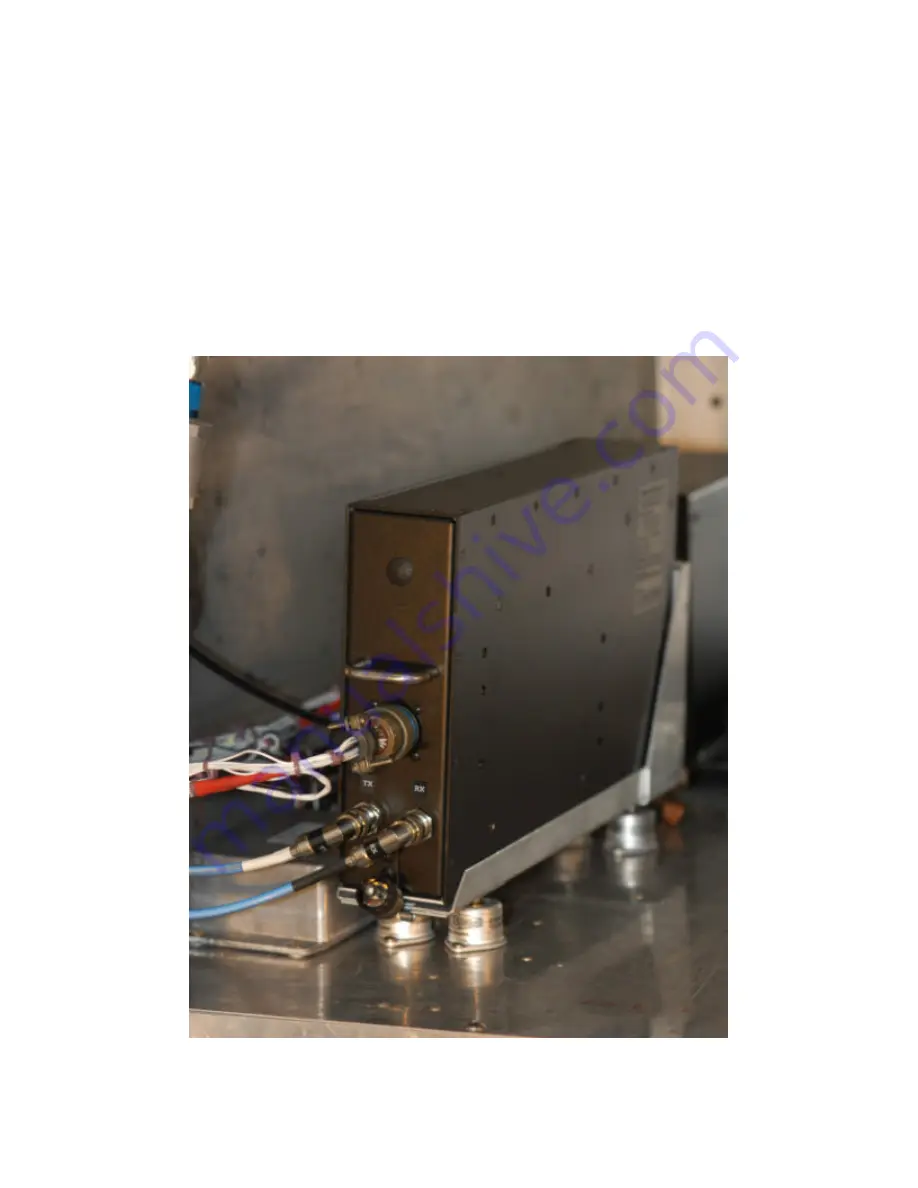
Prepare the mounting holes and secure the equipment-mounting tray. Place the RCOM-100 into
the mounting tray and secure it with the lockdown knob.
RCOM-100 and VC28 Mounting
Summary of Contents for RCOM-100
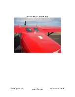
Page 9: ...ARNAV Systems Inc 8 Document No 570 8050B 27 November 2002 Antenna Mount Outside View ...
Page 17: ...ARNAV Systems Inc 16 Document No 570 8050B 27 November 2002 Appendix A Drawings ...
Page 21: ......
Page 27: ...ARNAV Systems Inc 17 Document No 570 8050B 27 November 2002 Appendix B PTA 12 Install Manual ...
Page 28: ......
Page 29: ......
Page 30: ......
Page 31: ......
Page 32: ......
Page 33: ......
Page 34: ......
Page 35: ......
Page 36: ......
Page 37: ......
Page 38: ......
Page 39: ......
Page 40: ......
Page 41: ......
Page 42: ......


