background image

G.  Step By Step 

AromaMist 

AromaMist 

AromaMist 

AromaMist 

Pump Installation (continued) 


Page 10 


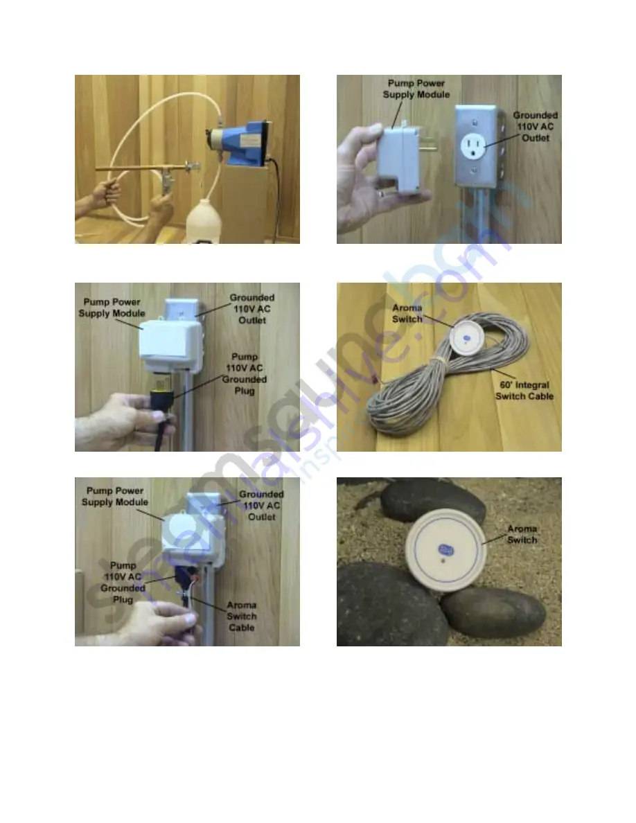
15. All pump connections should appear 
as detailed above.  Steam head shown 
for illustration purposes only. 


17. Plug in pump 110V AC power supply 
cord to power supply  module. 


16. Run a 110V AC grounded outlet 
within 6’ of pump installation location 
and insert pump power supply module. 


18. Locate pump switch with integral 3-
pin 60’ low voltage cable


19. Cut a 1

” hole in desired switch 

installation location and run control 
cable from switch mounting hole to 
power supply module 3-pin connection 
terminal pressing firmly to affix cable.  
See page 6 for control installation 
details. 


20. After testing pump switch for 
operation, secure in newly created 1

” 

diameter hole using 100% clear silicon 
and let dry for 24 hours prior to use. 


Summary of Contents for AI-5

Page 1: ...AromaMist AromaMist AromaMist AromaMist Pump Model AI 5 Installation and Operation Manual rev 3z 9505...

Page 2: ...on 3 II Safety and Operating Information 3 III Pump Package Contents 4 IV Installation A Location 4 B Mounting The Pump 4 C Electrical 5 D Plumbing 5 E Control Aroma Switch 6 F Typical Installation 7...

Page 3: ...tem II Safety and Operating Information CAUTION Please read this manual in its entirety prior to installing or operating the AromaMist AromaMist AromaMist AromaMist pump system A Chemical Compatibilit...

Page 4: ...ient to the aroma oil supply and a source of power for the pump Do not install the pump in a location where the ambient temperature exceeds 100 degrees Fahrenheit or where water can freeze A location...

Page 5: ...utput This predictability can only be maintained if all fitting sizes remain unaltered Do not attempt to reduce tubing size All tubing connection should be double checked to insure against leakage CAU...

Page 6: ...ing an aroma switch mounted inside the steam room is most preferred 2 Mounting Aroma Switch Make a 1 diameter hole in desired control location Route the aroma switch integral control cable from the wa...

Page 7: ...ist AromaMist AromaMist AromaMist Pump Installation 1 Verify carton components and mount pump on a level surface See details on locating the pump on page 4 of this manual 2 Locate AromaMist AromaMist...

Page 8: ...ads 7 Thread suction tubing through aroma container 7 16 hole and insert components into aroma oil container Foot valve should remain vertical and resting on aroma container bottom 4 Beginning with th...

Page 9: ...bove 13 Locate 3 function valve apply Teflon tape or joint compound to NPT threads and secure 3 function valve in bottom of T 10 Cut required length of discharge tubing remove discharge valve tubing n...

Page 10: ...of pump installation location and insert pump power supply module 18 Locate pump switch with integral 3 pin 60 low voltage cable 19 Cut a 1 hole in desired switch installation location and run control...

Page 11: ...ed on the pump panel face This will initiate the priming process where aroma oil will be drawn at a faster rate to fill the suction and discharge tubing Releasing prime button will stop priming proces...

Page 12: ...ue steam shower condensation and moisture will cause the steam room floor and other surfaces to become slippery Installation of non skid floor materials and caution while walking is always recommended...

Page 13: ...ting and stopping of aroma oil will not adversely affect the AromaMist AromaMist AromaMist AromaMist pump The AromaMist AromaMist AromaMist AromaMist pump has no adjustment for aroma oil flow rate For...

Page 14: ...o prime Inspect check valves in fluid end for cleanliness Clean or replace as necessary Inspect suction tube through its full length to assure that there are no kinks or other restrictions Check fluid...

Page 15: ...Page 15...

Reviews: