0MNA080A55-GB REV 01 page 21 / 75
3.3.3 REMOTE COMMANDS AND ALARMS
-C-
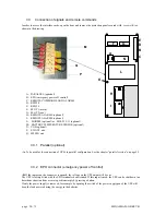
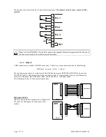
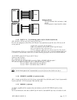
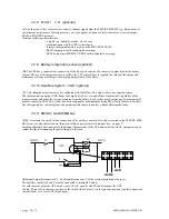
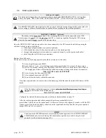
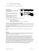
The card is equipped with a terminal board with 12 positions which has the following:
POWER SUPPLY
1 power supply 12Vdc 80mA(max.) [pins 10 and 11];
ALARMS
3 potential-free change-over contacts for alarms;
COMMAND
1 command programmable from the panel [pins 11 and 12];
The functions of the three contacts and the command may be reprogrammed via the display panel. The ALARMS
and the COMMAND are factory-set in the following way:
- ALARMS
- RL1
Bypass / fault, the contact changes position when the UPS switches the load onto
the by-pass line either during normal operation (e.g. due to overload) or as a
result of a fault in the inverter stage;
- RL2
Battery discharging, the contact changes position when the load is powered from
the battery due to a mains power failure;
- RL3
End of battery discharge, the contact changes position when, during a mains
outage, the remaining time for battery discharge has reached the minimum value
defined. Once this time has passed, the load will remain unpowered (the factory-
set end of discharge pre-alarm value is 5 minutes);
- COMMAND
IN1
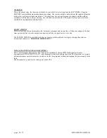
Inverter OFF. Connect pin 11 to pin 12 (for at least 2 seconds) .
- In “NORMAL OPERATION”,
if the INVERTER OFF command is received, the UPS switches the power
supply of the load onto the by-pass line (load is not protected should there be a
mains outage).
- In “EMERGENCY OPERATION”,
if the STOP INVERTER command is received, the UPS shuts down (load is not
powered).
With the jumper present, the UPS remains switched on the by-pass line when the
mains power supply is restored.
With no jumper present, the UPS will restart in NORMAL OPERATION.


