background image


0MNA080A55-GB  REV 01                                                                                                                   page   29 / 75 


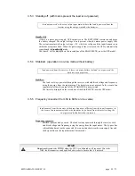
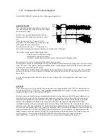
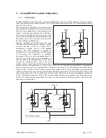
3.5.3  Standby-off  (with mains present the load is not powered)  


load not powered, in the event of an input mains failure the load is powered from the 

inverter using the energy stored by the batteries. 


Standby-Off:


 if there is a mains power supply, UPS output is zero. The RECTIFIER  remains on and keeps 
the battery charged. The output voltage is only present when the mains power supply fails. 
The system remains with output voltage  = 0V  while the voltage and the input frequency are 
within the acceptance field.  When the power supply line is restored, the UPS is automatically 
repositioned in 

Standby-Off

 mode. 

The letter 

F

 will be displayed on the second line of the BASIC MENU, near the UPS model. 


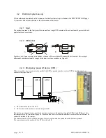
3.5.4  Stabilizer  (operation in on-line mode without battery) 


load powered from the inverter, if there is a mains failure the load is not powered, the 

batteries are not present. 


Stabilizer:


The load is always powered through the inverter, with stabilized voltage and frequency, 
using the energy from the input mains. The batteries are not present. In the event of an 
input mains failure, the output of the STABILIZER is not powered.  

The letter 

S

 is displayed on the second line of the BASIC MENU, near the UPS model. 


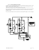
3.5.5  Frequency converter (from 50 to 60Hz or vice versa) 


load powered from the inverter with output frequency different from the input frequency; in 

the event of an input mains failure the load may be  powered from the inverter using the 

energy stored by the batteries, if present. 


Frequency converter:


MAINS  present, load powered.  The load is always powered through the inverter, with 
stabilized voltage and frequency, using the energy from the input mains.  The by-pass line 
is disabled and must not be connected (the connections between the main supply line and 
the by-pass line on the input bars must be removed). 


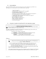
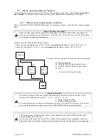
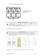
SWMB 


Do not use disconnector SWMB when the UPS  is configured as a Frequency Converter. 

N.B.

: the disconnector can be padlocked in order to ensure that it is not used. 


Summary of Contents for SENTRY MPS-HP

Page 1: ...SENTRY MPS HP USER MANUAL U UN NI IN NT TE ER RR RU UP PT TI IB BL LE E P PO OW WE ER R S SU UP PP PL LY Y 100 to 250 kVA Three Phase Output ...

Page 2: ...page 2 75 0MNA080A55 GB REV 01 AROS s r l Via Somalia 20 200032 Cormano MI Italy Tel 39 02 66327 1 Fax 039 02 66327 231 e mail info aros it www aros it ...

Page 3: ...d to read this part of the manual Protective equipment to be worn No maintenance operations must be carried out on the device without wearing the Personal Protective Equipment PPE described below Personnel involved in the installation or maintenance of the equipment must not wear clothes with wide sleeves or laces belts bracelets or other items that may be dangerous especially if they are metallic...

Page 4: ...on covers personnel that in addition to the requirements listed above for a general operator must also 1 have been suitably trained by the manufacturers or their representative 2 be aware of installation assembly repair and service procedures and have a specific technical qualification 3 must have a background of technical training or specific training relating to the procedures for the safe use a...

Page 5: ...r switches The disconnecting switch or battery fuse located in the battery cabinet should also be opened Before carrying out any operation always measure the voltage with a multimeter to ensure that there are no dangerous voltages There are dangerous voltages inside the equipment even when the input and battery switches are in the open position personnel must wait around ten minutes for the capaci...

Page 6: ...irements set out in this user manual Instructions for use The SENTRY MPS HP is an Uninterruptible Power Supply for professional use in industrial or commercial environments Shielded cables must be used for the connection to REMOTE and RS232 connectors Warning Sale of this product is reserved for competent installers Installation restrictions or additional measures may be necessary in order to avoi...

Page 7: ...PO connector emergency power off control 20 3 3 3 REMOTE COMMANDS AND ALARMS 21 3 3 4 RS232 22 3 3 5 SLOTS 1 2 the following cards may be inserted optional 23 3 3 6 REMOTE ALARMS 2 optional cards 23 3 3 7 MODEM optional 23 3 3 8 MULTI I O optional 24 3 3 9 Battery temperature sensor optional 24 3 3 10 Dual Bus System UGS optional 24 3 3 11 SWOUT and SWMB aux 24 3 4 Start up procedure 26 3 4 1 Batt...

Page 8: ...5 Menu key 3 key Controls 57 5 4 5 1 Keys menu 3 2 battery test 57 5 4 5 2 PERSONALIZATIONS 58 5 4 5 3 Keys menu 3 5 CODE 436215 58 5 4 5 4 RATED OUTPUT VOLTAGE 59 5 4 5 5 BATTERY 59 5 4 5 6 PRE ALARM 60 5 4 5 7 AUTO OFF VA 62 5 4 5 8 AUTO OFF Timer 62 5 4 5 9 BY PASS VOLTAGE FIELD 63 5 4 5 10 BY PASS FREQUENCY FIELD 63 5 4 5 11 MODEM 63 5 4 5 12 DIAL SEND MODEM 64 5 4 5 13 RS232 64 5 4 5 14 ECHO ...

Page 9: ... weight and dimensions of the various items making up the packing list are shown Check the state of the device by means of a visual inspection of both the inside and the outside Any dents seen mean that it has suffered knocks during shipping which could compromise the normal operation of the device 1 2 Storage In the following situations installation not immediately after delivery de installation ...

Page 10: ...ert the forks of the fork lift truck in the lower part of the device from the front or back and ensure that they stick out about 30 cm on the other side If a transpallet is used raise the device only as much as is strictly necessary 2 Secure the device to the transpallet or fork lift before moving it Risk of overturning In order to avoid the risk of the device overturning ensure that it is firmly ...

Page 11: ...wing data the position of the holes in the base to secure the device to the floor if applicable the view of the floor support for the sizing of a structure to raise the cabinet if applicable the position of cable entry the position of the fans on the top of the UPS for the positioning of a structure to convey the warm air discharged by the equipment outside the premises if applicable the input out...

Page 12: ...r battery premises The premises housing the battery cabinet must have sufficient air circulation to ensure that the concentration of hydrogen issued during battery charging is kept below the danger limit The air change in the premises should preferably be provided by natural ventilation otherwise by forced ventilation The standard EN 50272 2 for air change envisages that the minimum opening must s...

Page 13: ...and the by pass line The protection device should be sized according to the situation as follows a Single power line The fuse represented with the letter F alone provides the protection for all three lines mentioned above b main power supply and separate by pass When there are two separate power lines the main power line and the by pass line two protection devices must be provided indicated with t...

Page 14: ...l be triggered rather than the fuse located at the UPS input This is known as selectivity and ensures that the remaining feeders maintain the power supply In order to select the correct protection devices to be inserted downstream of the SENTRY MPS HP the following two operating modes have to be taken into consideration mains power supply and battery power supply With mains power supply the output...

Page 15: ...tween at least five feeders each sized at 20 of the rated power selectivity with mains power supply only since it is considered unlikely that after a first fault a second fault will occur in the limited time of operation from the battery it is sufficient to share the output between two lines each sized for 50 of the rated power 3 1 3 Differential If the SENTRY MPS HP protection against electric sh...

Page 16: ...feed on the input line due to an internal fault This protection device works by switching off the inverter if the current flow is faulty thereby causing voltage backfeed on the by pass line during operation from the inverter If the fault occurs when the UPS is operating from the battery the load will not be powered Should it be required to avoid the shutting down of the inverter in order to keep t...

Page 17: ...ERATE WITHOUT AN EARTH CONNECTION Before making the connection open all the switches on the device and ensure that the UPS is completely isolated from the power sources battery and AC power line More specifically check that the UPS input line or lines are completely isolated the battery cabinet disconnector fuse if present is open all the UPS disconnectors SWIN SWBY SWOUT and SWMB are in the open ...

Page 18: ...mer must be inserted either on the mains supply line or on the by pass line as shown in the drawings Single power line without neutral main power supply and separate by pass without neutral MAINS LINE UPS LOAD 3Ph N or OPTIONAL MAINS LINE UPS LOAD 3Ph N BY PASS LINE or OPTIONAL ...

Page 19: ...arted up regularly During connection to the UPS the disconnector must stay in the open position Up to 5 battery cabinets can be connected in parallel in accordance with the diagram below Cabinet disconnector For systems with 3 or more battery cabinets up to 5 units use a cabinet with a disconnector where the cables can be parallel connected refer to the marketing department For the sizing of the c...

Page 20: ...ional P SWOUT aux Q SWMB aux 3 3 1 Parallel optional A To be used for the connection of UPSs in parallel configuration See the chapter parallel version on page 35 3 3 2 EPO connector emergency power off control B If the jumper on the connector is opened the voltage on the UPS output will be cut The UPS is factory fitted with the EPO terminals shortcircuited If this input is used the UPS can be shu...

Page 21: ...g the contact changes position when the load is powered from the battery due to a mains power failure RL3 End of battery discharge the contact changes position when during a mains outage the remaining time for battery discharge has reached the minimum value defined Once this time has passed the load will remain unpowered the factory set end of discharge pre alarm value is 5 minutes COMMAND IN1 Inv...

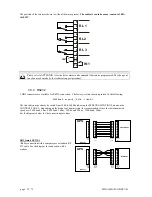
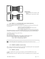
Page 22: ...ZATIONS menu on the CONTROL PANEL Depending on the distance of transmission the recommended values for the transmission speed are 9600 baud 50m 4800 baud 100m 2400 baud 200m 1200 baud 300m See the diagrams below for the connection procedure DB9 female RS232 1 D For connection with a computer use a standard RS 232 cable See the diagram for connection with a modem 1 2 3 4 5 6 7 8 9 1 2 3 4 5 6 7 8 9...

Page 23: ... network The main function of this device is to integrate the SENTRY MPS HP into the LAN network ensuring a high level of reliability of communication with the server to enable full management and control of the SENTRY MPS HP MULTICOM card on SLOT 1 main or SLOT 2 aux This device may be used to add a serial port to the UPS monitor the UPS using MODBUS JBUS protocol on RS485 or PROFIBUS Multicom 40...

Page 24: ...ion option UGS keeps the outputs of the two systems always synchronized regardless of the input variations and when the system is running from the battery Each system may be made up of a maximum of 4 parallel connected UPSs This system has been designed for configurations using STSs Static Transfer Switches since this guarantees switching from one uninterruptible source to another without affectin...

Page 25: ...0MNA080A55 GB REV 01 page 25 75 Page blank ...

Page 26: ...d be carried out in this order 1 close input disconnector SWIN 2 press button 1 twice select the language and then press button 8 to return to the basic menu 3 after a few seconds messages on the status of the UPS will start to be shown on the first line of the display panel these will include the following message relating to the battery disconnector Wait DO NOT connect the BATTERY 4 close by pas...

Page 27: ...heck operation the battery does not need to be charged With the UPS in normal operation open switch SWIN located at the UPS input rectifier The buzzer should sound immediately with 5 ON while OUT green LED and BATT yellow LED on the Signals and Commands Panel should be constantly on Check that the load connected to the UPS is powered In this state the power supplied to the load is the same as the ...

Page 28: ...e place the by pass line has to remain in the acceptance field for the time set In Standby On mode the rectifier remains powered and keeps the batteries charged If the by pass line voltage or the frequency go out of the acceptance field the load is automatically switched onto the inverter output With Standby On operation the energy dissipated by the system can be reduced leading to considerable sa...

Page 29: ...bilizer The load is always powered through the inverter with stabilized voltage and frequency using the energy from the input mains The batteries are not present In the event of an input mains failure the output of the STABILIZER is not powered The letter S is displayed on the second line of the BASIC MENU near the UPS model 3 5 5 Frequency converter from 50 to 60Hz or vice versa load powered from...

Page 30: ...he sequences of operations to be carried out to place the UPS in maintenance bypass are shown below The procedure varies depending on the initial state of the UPS SENTRY MPS HP in NORMAL OPERATION procedure a the power supply to the load is not interrupted in any way SENTRY MPS HP with output not synchronized with the by pass line procedure b the power supply to the load is interrupted therefore t...

Page 31: ...operations restart the UPS following the instructions in the section on START UP PROCEDURE see page 26 Then open disconnector SWMB if it was previously closed The SENTRY MPS HP will return to NORMAL OPERATION 3 8 UPS and load shutdown This operation will cause the shutdown of the load connected on the output In parallel versions each procedure must be carried out on all the UPSs open the switch of...

Page 32: ...MB SWOUT Inverter Static switch Rectifier Signallings and command panel Backfeed protection Control circuit with microprocessor EPO Signalling and alarm remote RS 232 1 line for PC RS 232 2 line for Modem DB9 female DB9 male 1 9 1 9 13 14 1 12 SLOT 1 SLOT 2 aux SWOUT aux SWMB batt temp sensor optional card optional card remove jumper for by pass line separate ...

Page 33: ...s also automatically effected to check the state of charge and to reintegrate the normal battery auto discharge BATTERY This is the energy reserve to power the load when power is no longer supplied to the UPS It is housed in one or more additional cabinets The battery cabinet must be provided with a sectioning device and a protection device magneto thermal switch or disconnector with fuses The loa...

Page 34: ...llows the synchronized switch automatic or manual and in zero time of the power supply to the load from a protected line inverter output to an unprotected line by pass line or vice versa The SENTRY MPS HP is provided with a device to prevent the backfeed of voltage to the input line after an internal fault known as BACKFEED PROTECTION MANUAL MAINTENANCE BY PASS SWMB This is a maintenance disconnec...

Page 35: ...formation is exchanged between the UPSs via a cable connecting them in a loop The loop connection provides redundancy in the connection cable communication in the cables between the individual units This is the most reliable means of connecting the UPS and also allows the hot insertion or disconnection of a UPS Each UPS has its own controller that continuously communicates with the whole system so...

Page 36: ...e differential switch inserted at the input of the whole system as shown in figure B 4 2 3 Emergency power off device EPO When several devices are connected in parallel the EPO command must be sent to all UPSs simultaneously as shown in the figure below a EPO terminal board on the UPS b EPO switch with auxiliary contacts not provided The button must have the same number of auxiliary contacts as th...

Page 37: ...t as the UPS consists of two disconnectors one for the output and one for the by pass these are sized for the total power of the system The new disconnector located on the by pass line S must be provided with auxiliary contacts one for each UPS The position of the contact is opposite to the position of the switch thus the contact must be closed when the disconnector is open The contacts of each di...

Page 38: ...responding output phases of each UPS L1 L2 L3 N The figure shows an example of three units connected in parallel A Power supply line B SENTRY MPS HP input terminal boards C SENTRY MPS HP output terminal boards D Load a1 a2 a3 c1 c2 c3 length of cables Length of the cables The sum of the lengths of the power supply and output cables must be the same for all units With reference to the drawing these...

Page 39: ...ted up regularly In the phase of connection to the UPS the disconnector must remain in the open position Several SENTRY MPS HPs connected to the same battery Disconnector cabinet For systems with 3 or more battery cabinets up to 5 units it is necessary to use a cabinet with a disconnector where the cables can be connected in parallel consult the commercial department For the sizing of the cables a...

Page 40: ...COMMANDS RJ45 flat adapter signals parallel card N B the SENTRY MPS HP may be provided with two versions of parallel card that differ in the type of switch used type 1 or type 2 The difference between the two switches is the position of the control lever Type 1 type 2 LED side connector side J1 RJ45 type connector J2 RJ45 type connector SW1 start position connector side type 1 LED side type 2 Cont...

Page 41: ...use a UPS that has been configured as a parallel unit on its own the signal card must be jumpered with the cable provided as shown below A UPS PARALLEL CABLE B RJ45 type connector C RJ45 flat adapter signal parallel card D LED on E SW1 start position two SENTRY MPS HPs in parallel D UPS1 LED on UPS2 LED off E SW1 start position UPS1 SW1 cont position UPS2 B B C A UPS D E B B C A UPS 1 D A UPS 2 E ...

Page 42: ...D on UPS2 LED off UPS3 LED off E SW1 start position UPS1 SW1 cont position UPS2 UPS3 To add other parallel UPSs a UPS PARALLEL CABLE must be added for each new UPS connected The signal connection must not be removed when one UPS is shut down B B C A UPS 1 D A UPS 2 E A UPS 2 ...

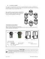
Page 43: ... B the UPS with a capital X B or P is the MASTER unit The X on the MASTER unit may be X B the parallel battery code has already been inserted Only the battery capacity value has to be inserted see below X P the parallel battery code must be inserted by pressing keys 3 5 in sequence on the control panel and the code 467123 repeat the same sequence to disable the parallel The UPSs connected to the o...

Page 44: ...he length of the cables and the rules on the length of the connections indicated in the section connections must be observed In the event of a mains power failure the load is passed onto all the parallel connected UPSs STAND BY OFF OPERATION In this mode if there is a mains power outage the devices share the load equally the load is not powered with the mains present STABILIZER WITHOUT BATTERY OPE...

Page 45: ...anel 2 Normal operation Slave units with message Parallel signal cable fault on the panel 3 Normal operation Slave units with message Parallel signal cable fault on the panel N B in this situation the load is powered correctly All the SENTRY MPS HP supply power to the load Let us assume that the signal cables between UPSs 1 3 and 2 3 are opened UPS STATUS 1 Normal operation Master unit with messag...

Page 46: ...s can power the load the system remains in normal operation and the maintenance can be carried out on UPS1 maintenance on the whole system The sequences of operations to be carried out to place the system in maintenance bypass are described below The procedures vary depending on the initial state All the UPS are in NORMAL OPERATION procedure a the power supply to the load is not interrupted in any...

Page 47: ...p The hot insertion and removal of the UPS can only take place if the system is configured with the RJ45 female RJ45 female shielded adaptor cable as shown in the figures below The hot insertion and removal of the UPS makes technical support easier and improves the reliability of the system With this procedure it is not necessary to shut down all the UPSs in order to add or remove a unit Hot inser...

Page 48: ...le RJ45 female shielded adaptor cable UPS BYPASS CABLE N B if the UPS to be removed has SW1 in the start position one of the other UPSs UPS 1 or UPS2 must be in the start position One UPS in the system must have SW1 in the start position and LED Phase I Shut down the UPS 3 that is to be removed Remove the signal cables of the UPS to be removed Phase II III Connect the RJ45 female RJ45 female shiel...

Page 49: ...0MNA080A55 GB REV 01 page 49 75 Page blank ...

Page 50: ...t power is correct since it is less than 100 VA and the output disconnector SWOUT is closed Flashing The system output is switched onto inverter the output power is greater than 100 VA or SWMB is closed Off The system output is switched onto automatic by pass or SWOUT is open 3 yellow BY PASS On The system output is switched onto the automatic by pass line Flashing The system output is switched on...

Page 51: ...explicitly by the message The Normal menu can be accessed by pressing the keys and is automatically returned to approx two minutes after the last key is pressed 5 3 Alarm messages Below is a list of the alarm messages that are shown on the first line of the display panel INTERFERENCE ON BY PASS LINE Alarm present when there is interference on the by pass line such as voltage peaks or harmonic dist...

Page 52: ...TO OFF is factory set at zero thus the alarm condition cannot be checked INTERNAL FAULT number Alarm codes used by the service TEMPORARY BY PASS WAIT This indicates that the load is powered from the by pass line and the system is in the phase prior to the automatic return to normal operation with power supply from the inverter This temporary operation may take place as an example during the start ...

Page 53: ...Alarm present when the command for total shutdown from the panel or through the RS232 connection COMMAND STORED has been inserted The system executes the shutdown command with a few seconds delay to allow for cancellation The command remains stored even during shutdown due to a power outage When the power supply is restored the system does not return to normal operation if the block that has been ...

Page 54: ...the inverter normal operation but from the mains through the by pass line The message OUT 100 VA changes to OUT SWMB when the load is powered through the maintenance by pass disconnector line and the output current cannot be provided The value 100 VA provided in the example is obtained from the measurement of the output current The number indicates the output current with the value relating to the...

Page 55: ...ting to the capacity of the battery connected and the stored value relating to the percentage of recharge prior to discharge The backup time shown should nevertheless be considered as indicative due to the many different factors affecting it If considerable differences are noted between the expected value and the actual time of a discharge with constant load the stored data relating to the battery...

Page 56: ...alue BY 230 230 230Vln 400V Measurement of the three input phase voltages of the by pass line with the concatenated voltage the average of the three values in brackets 50 1Hz Frequency of the by pass line BATT xxxV battery voltage value 0 0A battery current positive with Battery discharging negative with battery charging i 230 230 230Vln inverter output voltage yyyVdc input inverter DC voltage Ts ...

Page 57: ...A new test is performed 60 sec after activation of the alarm and if the result is negative the alarm is activated once again for another 60 sec The alarms continue to halve the charge value stored until the calculated battery voltage is less than the voltage actually measured In practice this battery control system produces an alarm each time the battery is seen to have less than half of the expec...

Page 58: ...d if present with the following sequence of keys from the basic menu 7 4 then by scrolling through the alarms with keys 7 and 8 The following message will be displayed System Autorestarting Disabled 1 Option 41 Tot active 1 8 next 5 4 5 3 Keys menu 3 5 CODE 436215 The code is no longer required for 2 minutes after it has previously been inserted The next menu can only be accessed by inserting the ...

Page 59: ...pacity It is important to insert the correct battery capacity value since this value is used by the system logic to calculate the backup time If not set otherwise this value is assumed to be equal to the UPS power e g at 100kVA the value set by default is 100Ah Battery type for high intensity discharge batteries change from value 1 normally pre set for normal batteries to value 2 value 3 is to be ...

Page 60: ...36215 4 315Vmin 336Vp 378Vs Pre alarm 5 min ADJUSTMENT 7 8 Press key 1 to exit the menu The menu above will appear with batteries of type 1 2 or 3 Voltage values Vmin Vp and Vs are not fixed values but are a function of the battery discharge current Vp Vmin 5V 10 battery current A battery capacity Ah Keys 7 and 8 can be used to decrease or increase the time to activate the pre alarm before the sys...

Page 61: ...current battery capacity in Ah Example for a 100Ah battery with a discharge current of 100A the regime is 1 The three values Vs Vmin and Vp are obtained from the discharge characteristic curve supplied from manufacturer relating to the battery discharge regime 1C has been determined Vs start of discharge voltage 1 intersection with the x axis battery terminal axis the value must be multiply for 40...

Page 62: ...e load before effecting the automatic return to normal operation The AUTO OFF function may be used to shut down the system during operation from battery simply by shutting down the output load In normal operation the AUTO OFF function may be used to reset consumption since the power circuits are deactivated the battery remains isolated and only the control circuits with consumption equivalent to a...

Page 63: ...xit the menu Keys 7 and 8 can be used to decrease or increase the value percentage of the field for the acceptance of the frequency at the by pass line input The choice is between the values 1 and 5 relating to the rated system value of 50 or 60 Hz 5 4 5 11 MODEM Press the following sequence of keys to access the menu 3 5 436215 7 4 MODEM enable 0 ADJUSTMENT 5 dial 6 send 7 8 Press key 1 to exit t...

Page 64: ...l when any alarm is verified 5 4 5 12 DIAL SEND MODEM Press the following sequence of keys to access the menu 3 5 436215 7 4 5 6 MODEM dial n 6543210 2 3 ADJUSTMENT 5 dial 6 send 7 8 Press key 1 to exit the menu Keys 7 and 8 can be used to decrease or increase the figure on which the cursor is positioned The cursor is moved by means of keys 2 and 3 and is indicated initially by the character _ Eac...

Page 65: ...ng sequence of keys to access the menu 3 5 436215 8 4 SMART ACTIVE S Stby 5 min Stby_ON 1 Adjustment 4 Sma OFF 5 6 7 8 Press key 1 to exit the menu When the Smart Active function is activated via key 4 Stby_ON goes to 1 The setting remains stored even during a shutdown due to a power failure There is a delay of 5 minutes before transfer to SMART ACTIVE mode For the description of the operation see...

Page 66: ...red a FFFF FFFF 2005 12 31 14 45 50 n 100 Return to the basic menu by means of key 1 Key 2 activates the submenu RECORDED VOLTAGES MEASUREMENTS Keys 3 4 and 5 keep their normal functions Key 6 activates the submenu 4 6 RECORDED CODES and allows the exchange of the stored alarm message with the display of the corresponding status codes at the time of the stored event and vice versa The status codes...

Page 67: ...uring a shutdown due to a power failure 5 4 8 CLOCK DATE TIME Press the following sequence of keys to access the menu 6 The DATE TIME menu is accessed via key 6 from the basic menu The display shows the current contents of the internal calendar and clock with the following format DATE TIME ymd h years months days hours minutes seconds The contents can be modified via the menu by inserting the pers...

Page 68: ...nnel The UPS is designed to power the load when it is disconnected from the power supply line High voltage is present inside the UPS even when the power supply and the battery have been disconnected After disconnecting the power supply line and the battery cabinet the trained personnel must wait around ten minutes for the capacitors to discharge before working on the inside of the equipment Ordina...

Page 69: ...0MNA080A55 GB REV 01 page 69 75 Page blank ...

Page 70: ...page 70 75 0MNA080A55 GB REV 01 Page blank ...

Page 71: ...absorbed 400 V A 126 151 200 250 312 Rated power absorbed 400 V kVA 87 104 138 173 216 Maximum current absorbed at full load and with battery recharging A 145 173 229 288 359 Maximum power absorbed at full load and with battery recharging kVA 100 120 159 199 248 Power factor at rated voltage 400 V and battery charge from 25 to 100 of the load 0 99 Current Harmonic Distortion THDi load rated load a...

Page 72: ...class 1 Current peak factor Ipeak Irms as per EN 62040 3 3 1 Voltage distortion with linear load 1 typical 2 max Voltage distortion with non linear load EN 62040 3 3 Stability of frequency with Inverter synchronized with the by pass mains 2 adjustable from 1 to 6 from control panel Stability of frequency with Inverter not synchronized with the by pass mains 0 05 Speed of frequency variation 1Hz se...

Page 73: ...om control panel Switching onto by pass with synchronized Inverter UPS in Normal Mode Approx 0ms Switching onto by pass with Inverter out of sync UPS in Normal Mode 20ms Switching from by pass to Inverter UPS in Stand by On mode from 2 to 5ms Delay in transfer onto Inverter after switching onto by pass 4 sec Power overload capacity of the by pass line kVA 110 for 60 minutes 125 for 10 minutes 150 ...

Page 74: ...ges on page 51 for an explanation of the alarms COMMAND name description Typical application Battery charge inhibition Disables the recharging of the battery keeping the recharge current to a minimum independently of the load This is done with the contact kept closed if reopened the command is cancelled When there is a generator this allows its output power to be used only to supply the load and n...

Page 75: ... the first time charging underway This is achieved by switching the contact from open to closed Activates manual remote battery charging Activation of block on Bypass Bypass command by means of blocking the inverter as a result of switching onto the by pass line N B The command is only executed if the by pass line is present with correct values This is achieved by switching the contact from open t...

Reviews: