background image

- 22 -


RISOLUZIONE DEI PROBLEMI 


PROBLEMA 

CAUSA POSSIBILE 

MISURE DA ADOTTARE 

L’interruttore ”ON/OFF” non è stato 
premuto fino in fondo 

Premere l’ interruttore ”ON/OFF” 
correttamente 

L’UPS non si 

accende 

Guasto dell’UPS 

Contattare l’assistenza tecnica 

Cavo di potenza allentato 

Inserire a fondo il cavo di 
alimentazione nella presa di rete  

Scattato interruttore termico di 
protezione 

Premere il tasto dell’interruttore di 
protezione per ripristinare il 
funzionamento dell’UPS 

Tensione di linea troppo alta, troppo 
bassa o black-out 

Condizione normale 

Gruppo di Continuità 

sempre in modalità 

batteria 

Guasto dell’UPS 

Contattare assistenza tecnica 

Batterie non completamente cariche 

Mettere sotto carica il Gruppo di 
Continuità per almeno 6 ore 

Durata di 

funzionamento con 

batteria tampone 

troppo breve 

Batterie danneggiate 

Sostituire le batterie 

Allarme sonoro 

sempre attivo 

Sovraccarico 

Eliminare i carichi non essenziali 

LED rosso ”batteria 

guasta” acceso 

Guasto batterie 

Sostituire le batterie 


Nel caso si verifichino problemi o malfunzionamenti diversi da quelli elencati oppure non si riesca ad 
effettuare le operazioni sopra descritte fare riferimento al servizio di assistenza tecnica allegando una 
documentazione completa del problema. 

Summary of Contents for Syncro 1000

Page 1: ...Manuale d uso User s Manual Bedienungsanleitung Manuel d utilisateur Manual de Usuario Syncro 800 1000 1500 2000 0MNUSC355A...

Page 2: ...Microsoft Windows and the Windows logo are trademarks or registered trademarks of Microsoft Corporation in the United States and or other countries...

Page 3: ...rsonale autorizzato La presa di uscita dell UPS potrebbe essere in tensione anche quando l UPS non collegato alla rete In caso di mancanza di rete funzionamento dell UPS in emergenza non staccare il c...

Page 4: ...conditions of danger and or to disconnect the UPS from the energy sources the mains and batteries unplug the mains cable from the mains socket or the rear of the UPS and power it off using the OFF but...

Page 5: ...die USV angeschlossen wird und oder die R ckseite der USV leicht zug nglich sein um eine schnelle Stromunterbrechung zu erm glichen Bei vorhandener Netzspannung und angeschlossenem Versorgungskabel si...

Page 6: ...S sur batteries ne pas d brancher le cordon d alimentation afin d assurer la continuit de la liaison de terre jusqu l utilisation Eviter que des liquides et ou autres substances trang res ne p n trent...

Page 7: ...aso que el UPS est trabajando de bateria no desconectar el cable de red De esta forma se continuar a garantizar la conexion a tierra a los aparados conectados Evitar que l quidos y u otros cuerpos ext...

Page 8: ...8 GR UPS UPS UPS LINE INTERACTIVE STEP WAVE UPS UPS c UPS UPS UPS UPS UPS UPS UPS UPS UPS UPS UPS OFF UPS 1 mA 3 5 mA 2 5 mA UPS...

Page 9: ...get f r utg ende str m p UPS kan vara sp nningssatt ven n r UPS inte r kopplad till eln tet F r att garantera en oavbruten jordanslutning f r inte elsladden tas ut ur n tuttaget d n tstr mmen r avbrut...

Page 10: ...ngsstopcontact van de UPS kan ook onder spanning staan als de UPS niet is aangesloten op het elektriciteitsnet Bij een stroomuitval werking van de UPS in een noodsituatie mag de voedingskabel niet wor...

Page 11: ...r com tens o mesmo quando a UPS estiver desligada da rede Em caso de falta de alimenta o el ctrica funcionamento da UPS em emerg ncia n o desligar o fio de alimenta o para poder garantir a continuidad...

Page 12: ...12...

Page 13: ...DESCRIZIONE UPS 14 VISTA FRONTALE 14 VISTA POSTERIORE 15 REQUISITI PER L INSTALLAZIONE 16 INSTALLAZIONE DELL UPS 16 FUNZIONAMENTO 17 ALLARMI 18 PORTA INTERFACCIA COMPUTER 19 SOSTITUZIONE BATTERIE 20...

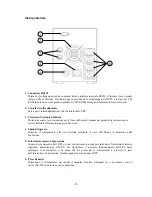
Page 14: ...giante 5sec UPS in funzionamento da batteria lampeggiante 1sec funzionamento da batteria in fine scarica o comando software di spegnimento attivato 3 Led batteria guasta rosso lampeggiante 1 2 sec bat...

Page 15: ...sione ai servizi telefonici Internet in maggiore sicurezza 4 Spina di ingresso Permette il collegamento alla rete elettrica mediante il cavo IEC Shuco in dotazione nella confezione 5 Interruttore temi...

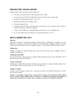
Page 16: ...ndi di conservare lo stesso nel caso l unit dovesse essere trasportata in futuro In caso contrario smaltirlo in maniera idonea Collocazione Installare il Gruppo di Continuit tenendo presente gli avver...

Page 17: ...sultare non funzionante se non installato correttamente Accertarsi che la linea telefonica in uscita dalla parete sia inserita nel connettore contrassegnato con IN e che il dispositivo da proteggere t...

Page 18: ...rimane acceso chiedere al distributore pi vicino di provvedere alla sostituzione delle batterie ALLARMI FUNZIONAMENTO DA BATTERIA Bip ogni 5 secondi In modalit di FUNZIONAMENTO DA BATTERIA il LED GIAL...

Page 19: ...ut down con UPS in funzionamento da batteria applicare un segnale positivo 5 15VDC tra questo ingresso pin 3 ed il comune pin 5 per almeno 20sec per effettuare lo spegnimento shut down B W Contatto ch...

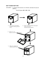
Page 20: ...ificato Modelli Syncro 800 1000 1500 1 Rimuovere la vite di fissaggio del pannello frontale posta sotto l UPS 2 Ruotare il pannello frontale di alcuni gradi Tirare verso il basso Rimuovere quindi il p...

Page 21: ...i verso il basso e poi in avanti 3 Rimuovere quindi il piccolo pannello 4 Rimuovere le viti 5 Ruotare il pannello frontale di alcuni gradi tirare quindi verso il basso per rimuovere il pannello fronta...

Page 22: ...ck out Condizione normale Gruppo di Continuit sempre in modalit batteria Guasto dell UPS Contattare assistenza tecnica Batterie non completamente cariche Mettere sotto carica il Gruppo di Continuit pe...

Page 23: ...110 immediatamente in caso di corto circuito Tipo Al piombo ermetica senza necessit di manutenzione Modello 2x12V 7Ah 2x12V 7Ah 2x12V 9Ah 3x12V 9Ah Tempo di ricarica tipico 6 8 ore BATTERIA Protezioni...

Page 24: ...24 SCHEMA A BLOCCHI GENERALE...

Page 25: ...25...

Page 26: ...27 DESCRIPTION OF THE UPS 27 FRONT VIEW 27 REAR VIEW 28 INSTALLATION REQUIREMENTS 29 INSTALLING THE UPS 29 OPERATION 30 ALARMS 31 COMPUTER INTERFACE PORT 32 BATTERIES REPLACEMENT 33 LOCATING FAULTS 3...

Page 27: ...llow flashing 5 second the UPS is operating in battery mode flashing 1 second the batteries are running low or the software shutdown command has been activated 3 Battery failure LED red flashing 1 2 s...

Page 28: ...overvoltages on telephone modem lines to ensure a more safe connection to telephone and internet services 4 Input Plug This is used to connect the UPS to the mains using the IEC Shuko cable supplied...

Page 29: ...ed to guarantee safe transportation of the unit so keep it for future use or dispose of it in the appropriate manner Installation Install the UPS ensuring that all the installation requisites are resp...

Page 30: ...tly Make sure that the telephone wall cable is inserted in the connector marked IN and that the cable of the unit to be protected telephone modem etc is inserted in the connector marked OUT Warning Th...

Page 31: ...es LED remains on call the nearest distributor for replacement batteries ALARMS BATTERY MODE Beep every 5 seconds In Battery Mode the yellow LED comes on and the UPS sounds an audio signal This stops...

Page 32: ...signal when the UPS is operating in Battery Mode apply a positive signal 5 15VDC between this input pin 3 and the common input pin 5 for at least 20sec in order to shutdown the unit B W Contact close...

Page 33: ...d service personnel Models Syncro 800 1000 1500 1 Remove the screw fixing the panel at the bottom of unit 2 First rotate to small angle then pull down You can disassemble the panel 3 Remove screw and...

Page 34: ...om of unit 2 Pull down to the limits then pull forward 3 Disassemble the little panel 4 Remove the screw 5 First rotate to small angle then pull down You can disassemble the panel 6 Remove screw and r...

Page 35: ...voltage too high too low or power black out Restore mains power supply UPS constantly operating in Battery Mode UPS failure Call technical support Batteries not fully charged Charge the UPS for at lea...

Page 36: ...exceeds 110 or immediately in the event of a short circuit Type Lead acid sealed maintenance free Model 2x12V 7Ah 2x12V 7Ah 2x12V 9Ah 3x12V 9Ah Typical recharge time 6 8 hours BATTERY Protection Prote...

Page 37: ...37 MAIN BLOCK DIAGRAM...

Page 38: ...38...

Page 39: ...G DER USV 40 VORDERANSICHT 40 R CKANSICHT 41 ERFORDERNISSE F R DIE INSTALLATION 42 INSTALLATION DER USV 42 FUNKTIONSWEISE 43 ALARME 44 COMPUTER SCHNITTSTELLE 45 AUSWECHSELN DER BATTERIEN 46 LOESUNG DE...

Page 40: ...etrieb gelb blinkend 5 Sek USV im Batteriebetrieb blinkend 1 Sek Batteriebetrieb am Entladungsende oder Software Anweisung zum Ausschalten in Betrieb gesetzt 3 LED Batterie besch digt rot blinkend 1 2...

Page 41: ...chlusses an Fernsprechdienste Internet mit gr sserer Sicherheit 4 Eingangsstecker Er erm glicht den Anschluss ans Stromnetz ber das Kabel IEC Schuko das in dem Satz mitgeliefert wird 5 Thermoschutzsch...

Page 42: ...gungen vorbereitet worden wir empfehlen daher diese aufzubewahren falls die USV in Zukunft bef rdert werden muss Ansonsten auf geeignete Weise entsorgen Aufstellung Das USV System unter Ber cksichtigu...

Page 43: ...stalliert wurde Sich vergewissern dass die Telefonleitung die aus der Wand kommt in den mit IN gekennzeichneten Verbinder gesteckt wird und dass die zu sch tzende Vorrichtung Telefon Modem usw in den...

Page 44: ...ip alle 5 Sekunden Im BATTERIEBETRIEB Modus schaltet sich die GELBE LED f r Batteriebetrieb ein und das USV System sendet einen akustischen Alarm aus Der Alarm wird eingestellt wenn das USV System in...

Page 45: ...gssignal mit der USV im Batteriebetrieb ein positives Signal 5 15VDC zwischen diesem Eingang Pin 3 und dem gemeinsamen Pin 5 f r mindestens 20 Sek anwenden um das Ausschalten Shut down auszuf hren B W...

Page 46: ...en Modell Syncro 800 1000 1500 1 Die schraube mit welcher die kleine abdeckplatte unten an der usv befestigt ist entfernen 2 Zuerst zum kleinen winkel drehen Dann nach unten ziehen Die platte kann aus...

Page 47: ...nen 2 Bis zum aeusserten punkt nach unten ziehen Dann nach vorn ziehen 3 Die kleine platte ausbauen 4 Schraube entfernen 5 Zuerst zum kleinen winkel drehen Dann nach unten ziehen Die platte kann ausge...

Page 48: ...r Zustand Das USV System ist immer im Batteriemodus Schaden der USV Mit dem technischen Kundendienst Kontakt aufnehmen Batterien nicht v llig geladen Das USV System f r mindestens 6 Stunde aufladen Be...

Page 49: ...lbar bei einem Kurzschluss aus Typ Bleibatterie dicht wartungsfrei Modell 2x12V 7Ah 2x12V 7Ah 2x12V 9Ah 3x12V 9Ah Typische Ladezeit 6 8 Stunden BATTERIE Absicherungen Ber hrungsschutz Anzeiger f r Bat...

Page 50: ...50 HAUPTBLOCKDIAGRAMM...

Page 51: ...51...

Page 52: ...ASI 53 VUE DE FACE 53 VUE ARRIERE 54 CONDITIONS D INSTALLATION 55 INSTALLATION DE L ASI 55 FONCTIONNEMENT 56 ALARMES 57 PORT INTERFACE ORDINATEUR 58 REMPLACEMENT DE LA BATTERIES 59 RESOLUTION DES PROB...

Page 53: ...c ASI en fonctionnement sur batterie clignotant 1sec fonctionnement sur batterie en fin de d charge ou commande logiciel d arr t activ e 3 Led panne batterie rouge clignotant 1 2 sec batterie remplace...

Page 54: ...aux services t l phoniques Internet avec plus de s curit 4 Fiche d entr e Elle permet d effectuer le branchement au r seau lectrique au moyen du c ble IEC Shuko fourni avec l appareil 5 Disjoncteur t...

Page 55: ...ppareil devrait tre transport l avenir Dans le cas contraire l liminer de mani re appropri e Mise en place Installer l Alimentateur Sans Interruption en tenant compte des avertissements cit s dans le...

Page 56: ...ll correctement S assurer que la ligne de t l phone en sortie du mur est bien branch e au connecteur IN et que le dispositif prot ger t l phone modem etc est bien branch au connecteur OUT Attention le...

Page 57: ...t de la batterie ALARMES FONCTIONNEMENT SUR BATTERIE Bip toutes les 5 secondes En mode FONCTIONNEMENT SUR BATTERIE le LED JAUNE de fonctionnement sur batterie s allume et l Alimentateur Sans Interrupt...

Page 58: ...e signal de shut down avec ASI en fonctionnement sur batterie appliquer un signal positif 5 15VDC entre cette entr e broche 3 et la commune broche 5 pendant au moins 20sec pour effectuer l arr t shut...

Page 59: ...qualifi Modeles Syncro 800 1000 1500 1 Retirer la vis qui bloque le panneau au fond de l unite 2 Tourner pour reduire au maximum l angle Ensuite tirer vers le bas Voue pouvez maintenant retirer le pan...

Page 60: ...ers le bas Puis tirer en avant 3 Demonter le petit panneau 4 Retirer vis 5 Tourner pour reduire au maximum l angle Ensuite tirer vers le bas Voue pouvez maintenant retirer le panneau 6 Retirer vis Enl...

Page 61: ...tion normale Alimentateur Sans Interruption toujours en mode batterie Panne de l ASI Contacter l assistance technique Batterie non compl tement charg e Mettre l Alimentateur Sans Interruption e charge...

Page 62: ...inale au bout de 5 secondes si 110 imm diatement en cas de court circuit Type Au plomb herm tique sans entretien Mod le 2x12V 7Ah 2x12V 7Ah 2x12V 9Ah 3x12V 9Ah Temps de recharge typique 6 8 heures BAT...

Page 63: ...63 SCH MA FONCTIONNEL PRINCIPAL...

Page 64: ...64...

Page 65: ...I 66 VISTA FRONTAL 66 VISTA POSTERIOR 67 REQUISITOS PARA LA INSTALACI N 68 INSTALACI N DEL SAI 68 FUNCIONAMIENTO 69 ALARMAS 70 PUERTO INTERFAZ ORDENADOR 71 SOSTITUCI N DE LAS BATER AS 72 RESOLUCI N DE...

Page 66: ...stellante 5 seg SAI en funcionamiento desde la bater a destellante 1 seg funcionamiento desde la bater a en fin de descarga o comando del programa de apagado activado 3 Led bater a averiada rojo deste...

Page 67: ...guridad la conexi n a los servicios telef nicos Internet 4 Enchufe de entrada Permite la conexi n a la red el ctrica mediante el cable IEC Shuco que se encuentra incluido en el paquete 5 Interruptor t...

Page 68: ...s de viaje aconsejamos pues conservarlo para el caso de que deba transportarse en el futuro En caso contrario deshacerse de l de la forma adecuada Colocaci n Instalar el SAI teniendo en cuenta las adv...

Page 69: ...mente Asegurarse de que la l nea telef nica de salida de la pared est insertada en el conector marcado con IN y que el dispositivo a proteger tel fono m dem etc est insertado en el conector marcado co...

Page 70: ...al distribuidor m s pr ximo y proceder a la sustituci n de la bater a ALARMAS FUNCIONAMIENTO DE BATER A Pitido cada 5 segundos En modo de FUNCIONAMIENTO DE BATER A el LED AMARILLO de funcionamiento d...

Page 71: ...do con el SAI en funcionamiento de bater a aplicar una se al positiva 5 15 VDC entre esta entrada pin 3 y el com n pin 5 durante al menos 20 seg para efectuar el apagado shut down B W Contacto cerrado...

Page 72: ...personal cualificado Modelos Syncro 800 1000 1500 1 Retirar el tornillo que sujeta el panel en la parte inferior de la unidad 2 Primero girar un poco Luego tirar hacia abajo Ya puede desmontar el pane...

Page 73: ...idad 2 Tirar hacia abajo hasta los l mites Luego tirar hacia adelante 3 Desmontar el peque o panel 4 Retirar el tornillo 5 Primero girar un poco Luego tirar hacia abajo Ya puede desmontar el panel 6 R...

Page 74: ...o apag n Condiciones normales SAI siempre en modo de bater a Aver a del SAI Ponerse en contacto con los servicios de asistencia t cnica Bater as no cargadas completamente Poner el SAI en carga durant...

Page 75: ...dos si 110 inmediatamente en caso de cortocircuito Tipo De plomo herm tica sin necesidad de mantenimiento Modelo 2x12V 7Ah 2x12V 7Ah 2x12V 9Ah 3x12V 9Ah Tiempo de recarga t pico 6 8 horas BATER A Prot...

Page 76: ...DIAGRAMA DE BLOQUE PRINCIPAL...

Page 77: ......

Page 78: ...Via Somalia 20 20032 Cormano Milano Italy Ph 39 02 66327 1 Fax 39 02 66327 231 E mail export aros it Internet www aros it 0MNUSC355A...

Reviews: