20
3645A Programmable Power Supply
ARRAY ELECTRONIC CO.,LTD 2002.3
3645A-TYPE USER’S MANUAL
Fig. 4-5 COM Port Failurely Opening Dialogue Frame
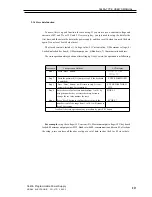
Set Default POWER Address:
The system will automatically be in the networking state after the start according to the default COM port and
the default POWER. It is just needed to enter the address in the “Default POWER” bar.
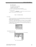
Set POWER Address:
Login in the identity of the “Manager” and select the existing COM port. Then the “ADDRESS” page key will
be available.
Fig. 4-6 POWER Address Set
In Fig. 4-6, enter the default address (245) of the lower machine and then click “READ”. If testing successfully,
the “NEW ADDRESS” and “WRITE” functions will be available. If testing failure, then the new address of the
power cannot be set and the prompting diagram as shown in Fig. 4-7 will be displayed. This time the communication
cable must be checked.
Fig. 4-7 Communication Failure
Explanation:
For the first time installation each POWER must be deployed with but one address so as to
communicate rightly. Set the parameter and select “OK” and it will enter into the common communication. The
default COM port is COM1 and the default POWER address is 1.
After the COM port and ADDRESS set, select the button and the system will start the communication. If the
communication is normal, the prompting information as shown in Fig. 4-8 will be displayed. And if the communica-
tion is failure, the prompting information as shown in Fig. 4-9 will be displayed.
Fig. 4-8 Normal Communication Fig.4-9 Failure Communication
Select the button and the system will stop the communication.
4.4 Run the Communication
4.5 Stop the Communication


