background image


1


USER’S MANUAL 


SWITCHING-MODE DC POWER SUPPLY 

                           ARRAY 366X 


ARRAY ELECTRONIC 


Summary of Contents for 366X

Page 1: ...1 USER S MANUAL SWITCHING MODE DC POWER SUPPLY ARRAY 366X ARRAY ELECTRONIC...

Page 2: ...s design and test environments Versatile Bench Top Features High definition liquid crystal display Full featured keyboard and knobs High efficient switching mode power supply The same continuous adjus...

Page 3: ...d off 2 Sense terminals Tests remote voltage the positive pole is in red the negative pole is in black 3 Earth ground terminal It is connected to the chassis and earth ground 4 Supply output terminals...

Page 4: ...current operation 20 Enter key Enter Confirms present setting values or option 21 Display screen Shows parameters and status of power supply 22 ERR annunciator When some error is detected ERR annunci...

Page 5: ...develops its rated outputs and responds to operation from the front panel properly Front Panel Operation It describes the use of front panel keys and knobs in detail and how to use them to operate the...

Page 6: ...ation Tutorial It describes basic operation of the power supply and gives specific details on the operation and use of ARRAY 366X power supplies Specifications It lists the power supply s basic specif...

Page 7: ...heckout 17 Voltage Output Checkout 17 Current Output Checkout 18 Chapter 3 Front Panel Operation 20 Front Panel Operation 20 Front Panel Operation Overview 20 Output on off 20 Constant Voltage Output...

Page 8: ...y 31 An Introduction to the SCPI Language 32 Command Format Used in This Manual 33 Command Separators 34 Using the MIN and MAX Parameters 34 Querying Parameter Settings 34 SCPI Command Terminators 35...

Page 9: ...s Byte Register 53 Status Reporting Commands 53 SCPI Conformance Information 55 SCPI Confirmed Commands 55 Device Specific Commands 57 Chapter 5 Application Programs 58 Application Programs 58 RS 232...

Page 10: ...erformance Specifications 64 Transient Response Time 65 Command Processing Time 65 Supplemental Characteristics 65 APPENDIX Error Messages 67 Error Messages 67 Execution Errors 68 Self Test Errors 71...

Page 11: ...ient switching mode supply features wide supply input voltage from 100 240AC high power factor and a minimum output of 0V Output voltage or current can be adjusted independently from front panel or co...

Page 12: ...irectly without opening the cabinet Correction factors are stored in non volatile memory You can guard against unauthorized calibration by using the Standard calibration protection function Installati...

Page 13: ...ss fan is used to cool the power supply by drawing cool air through the two sides and exhausting the heat through the fan outlet on the rear panel Sufficient space must be left at the rear and two sid...

Page 14: ...features for later use it is suggested that both the experienced and the inexperienced users should read this chapter prior to operation Preliminary Checkout ARRAY 366X power supply can be used from a...

Page 15: ...p 1 Remove the fuse holder below AC power inlet Step 2 Replace the fuse with the correct one that meets the requirements Step 3 Put back the fuse holder For 115V AC operation 10AT fuse must be used Fo...

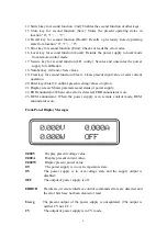
Page 16: ...Self test accomplished If there is no error or abnormity has been detected during self testing the supply will enter into power on reset state and the output will be disabled In this figure OFF indic...

Page 17: ...control on front panel for the supply Knob Checkout When the power supply output is on and the display is in monitor mode move the blinking digit to voltage value displayed by pressing the key Left T...

Page 18: ...the test lead 4 Adjust the voltage limit value to 1 0 V Adjust the voltage limit to 1 0 V to assure CC operation Please see related chapters about voltage and current setting from front panel in this...

Page 19: ...st the knob until the ammeter indicates 0A and then until the ammeter indicates the maximum rated value If an error has been detected during the output checkout procedures the ERROR annunciator will t...

Page 20: ...e output of the power supply is enabled CV CC or Unreg will be displayed in the lower right corner of the display CV indicates that the supply source is in constant voltage state CC indicates that the...

Page 21: ...r supply Press the Power on off button in the front panel The power supply will go into power on reset state namely the power supply is off 3 Setting desired output voltage The desired output voltage...

Page 22: ...ose a higher current limit value 3 4 Constant Current Output Setting When the power supply is in constant current mode the current will output at a constant value and it will not change with the load...

Page 23: ...the wrong value to input again Press Enter key to confirm the current setting value 2 Using Left Right keys knob and Enter key to input Press Iset to enter into current setting state Press Left Right...

Page 24: ...p Bit 1 2 Stop Bit 1 2 RS232 Interface Flow Control On Off Flow Control On Off USB Interface Selecting USB GPIB Interface GPIB Address 5 GPIB Address Address Value Notes Except the parameters about kn...

Page 25: ...ied by Location 1 Step Operational Details Display Information 1 Set voltage to 30V Then turn off the power supply 30 000V 0 000A 0 000W OFF 2 Press 2nd Recall keys to enter into recall menu Recall 0...

Page 26: ...r supply will disable its output and beep to give an alarm the display reveals the reason for the unusual condition and the power supply enters into abnormal latched state Except specific operations t...

Page 27: ...recision But it is suggested that the power should not be calibrated frequently This section mainly introduces how to unsecure the power supply and the detailed procedures of manual calibration Calibr...

Page 28: ...ch mode calibration is completed Press Clear key to exist calibration state 3 1 CV Mode Calibration In this mode three voltage points 0 5V 22V 34 5V take 3662A as example should be calibrated 3 1 1 Wi...

Page 29: ...to verify and then the display will show as follows Input the value you read from KEITHLEY 2000 which is retained to four decimal places Press Clear key to remove the wrong input value of current digi...

Page 30: ...45 which is retained to four decimal places Press Clear key to remove the wrong input value of present digit Then press Enter key to confirm 3 2 4 9A Calibration Press Enter key to verify and then th...

Page 31: ...z System Related Commands z Calibration Commands z RS 232 Interface Commands z The SCPI Status Registers z Status Reporting Commands z An Introduction to the SCPI Language z Halting an Output in Progr...

Page 32: ...nstruments The detailed techniques used to program the power supply over the remote interface are introduced in the following sections SCPI commands are based on a hierarchical structure also known as...

Page 33: ...r the keyword CURRent As you can use the mixture of upper or lower case letters for the commands CURR Curr and CURr are all acceptable Notice that the upper case letters are indispensable For example...

Page 34: ...ithin the same subsystem as shown below SOUR VOLT MIN CURR MAX The following two commands have the same effect as the above command SOUR VOLT MIN SOUR CURR MAX Use a colon and a semicolon to link comm...

Page 35: ...lso accepted SCPI Parameter Types The SCPI language defines several different data formats to be used in program messages and response messages Numeric Parameters Commands that require numeric paramet...

Page 36: ...le quote You can include the quote delimiter as part of the string by typing it twice without any characters in between The following command uses a string parameter DISPlay TEXT quoted string Output...

Page 37: ...SOURce TRG System Related Commands DISPlay WINDow STATe OFF ON STATe TEXT DATA quoted string TEXT DATA TEXT CLEar SYSTem BEEPer IMMediate ERRor VERSion IDN RST TST SAV 1 2 3 RCL 1 2 3 Calibration Comm...

Page 38: ...ue INSTrument ISUMmary n ENABle SYSTem ERRor CLS ESE enable value ESE ESR OPC OPC PSC 0 1 PSC SRE enable value SRE STB WAI RS 232 Interface Commands SYSTem LOCal REMote RWLock Simplified Programming O...

Page 39: ...command shown in the above example which shows when some individual parameter is changed there is no need to enter the whole setting parameters as the above example just enter some specified parameter...

Page 40: ...he setting range please consult the relevant current parameters listed in the table of Programming Ranges and Output Identifiers section When the voltage and current are set the DEF MIN MAX represents...

Page 41: ...ntifier is not specified the voltage of the currently selected output is returned Output on off and Tracking Operation Commands Output STATe OFF ON This command enables or disables the outputs of the...

Page 42: ...affected by subsequent CURRent commands SOURce CURRent LEVel TRIGgered AMPLitude MIN MAX This query checks and returns the presently programmed triggered current level If no triggered level is program...

Page 43: ...triggered voltage level If no triggered level is programmed the VOLTage value is returned VOLTage TRIGgered Return the VOLTage value or the set triggered voltage level of the selected output VOLTage...

Page 44: ...e trigger source from the USB RS 232 or GPIB interface The operation has been introduced before Immediate Triggering 1 Select the internal immediate trigger source by sending the following command TRI...

Page 45: ...n to the local state from the remote interface press any key except for the number keys knobs Resolution Clear Enter and Track keys or power on reset key to switch to the display status automatically...

Page 46: ...represent the year of the version and the V represents a version number for that year for example 1995 0 IDN This query command reads the power supply s identification string The power supply returns...

Page 47: ...This command can only be used after calibration is unsecured It enters a current value of a selected output that you obtained by reading an external meter You must first select a calibration level CA...

Page 48: ...ust be selected and entered The power supply then computes new voltage calibration constants which are then stored in internal memory CALibration VOLTage LEVel MINimum MAXimum Before using this comman...

Page 49: ...t is set subsequent state changes are ignored Bits in an event register are automatically cleared by a query command of that register such as ESR Or STAT QUES EVEN or by sending the CLS command A rese...

Page 50: ...ESE Output Buffer Operation Complete Query Error Device Depenent Error Execution Error Command Error Power On Serial Poll SPOLL SRE value SRE STB The Questionable Status Register The questionable stat...

Page 51: ...y the event register with STATus QUEStionable EVENt Status Questionable Event register command The questionable status enable register is cleared when you execute STATus QUEStionable ENABle 0 command...

Page 52: ...vent register is cleared when 1 You execute the CLS clear status command 2 You query the event register using the ESR Event Status register command For example if 28 4 8 16 is returned when you query...

Page 53: ...will clear only bit 5 in the status byte summary register For example if 24 8 16 is returned when you query the status of the Status Byte register it is convinced that QUES and MAV conditions have occ...

Page 54: ...e value This command enables or disables bits in the questionable status event register The selected bits are then reported to the status byte STATus QUEStionable ENABle This command queries the quest...

Page 55: ...tatus byte summary register The STB command is similar to a serial poll but it is processed like any other instrument command The STB command returns the same result as a serial poll but the Request S...

Page 56: ...MIN MAX CURRent LEVel TRIGgered AMPLitude MIN MAX VOLTage LEVel IMMediate AMPLitude voltage MIN MAX VOLTage LEVel IMMediate AMPLitude MIN MAX VOLTage LEVel TRIGgered AMPLitude voltage MIN MAX VOLTage...

Page 57: ...umeric value CURRent LEVel MIN MAX SECure CODE new code SECure STATe OFF ON voltage SECure STATe STRing quoted string STRing VOLTage DATA numeric value VOLTage LEVel MIN MAX MEASure SCALar CURRent DC...

Page 58: ...estore and receive the data array OPEN COM1 9600 N 8 2 RS LF PE FOR RANDOM AS 1 LEN 1000 Baud Rate 9600 Parity Check None Data Bit 8 Stop Bit 2 RS sending RTS signal is forbidden LF a carriage return...

Page 59: ...send instant information to the display At the same time the control circuit also receives and returns the corresponding values over the remote interface The remote interface is isolated from the cont...

Page 60: ...rrent setting The supply is in constant current CC mode and the voltage setting acts as a voltage limit Unregulated State If the power supply goes into a operation mode that is neither CV nor CC the p...

Page 61: ...iple loads to the power supply each load should be connected to the output terminals with separate connecting wires This minimizes mutual coupling effects between loads and takes full advantage of the...

Page 62: ...ccurately read back the voltage at the load Considerations During the operation of the power supply various problems may occur because of the difference in connected loads which will be introduced as...

Page 63: ...fications for the output the current limit should be set greater than the peak current expected or the supply may go into CC mode or unregulated mode Reverse Current Load An external source is not all...

Page 64: ...rature of the components is the better the reliability is When the power supply is in operation an internal fan installed in the rear of power supply can keep the temperature of components low To assi...

Page 65: ...5mVrms 15mVrms 20mVrms Voltage peak to peak value 10mVp p 10mVp p 14mVp p 80mVp p 80mVp p Current 10mArms 8mArms 6mArms 5mArms 4mArms Common Mode Current 1 5mArms 1 5mArms 1 5mArms 1 5mArms 1 5mArms...

Page 66: ...al Characteristics Output Programming Range maximum programmable values 3661A 3662A 3663A 3664A 3665A Voltage 0 20 2V 0 35 2V 0 80 2V 0 120 2V 0 200 2V Current 0 25A 0 14 5A 0 6 5A 0 4 2A 0 2 5V Tempe...

Page 67: ...c Full load Down 50msec 50msec 50msec 60msec 60msec No load Up 50msec 50msec 50msec 60msec 60msec No load Down 200msec 200msec 300msec 300msec 500msec AC Input Ratings AC100V 240V 47Hz 63Hz 750VA Max...

Page 68: ...command has been executed The RST reset command does not clear the error queue All error records will be lost when the power is turned off Front Panel operation If the ERROR annunciator is on press t...

Page 69: ...mnemonic too long A command header was received which contained more than the maximum 12 characters allowed 113 Undefined header A command was received that is not valid for this power supply You may...

Page 70: ...system is initiated by INIT IMM command then triggered by TRG 222 Data out of range A numeric parameter value exceeds the valid range for the command Example TRIG DEL 3 223 Too much data A character s...

Page 71: ...rface 430 Query DEADLOCKED A command was received which generates too much data to fit in the output buffer and the input buffer is also full Command execution continues but all data is lost 501 Isola...

Page 72: ...Cal checksum failed string data 745 Cal checksum failed DAC cal constants 746 Cal checksum failed readback cal constants 747 Cal checksum failed GPIB address 748 Cal checksum failed internal data 750...

Page 73: ...73 759 Cal checksum failed store recall data in location 9 VER 20150323...

Reviews: