53
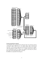
output buffer, including any pending queries, will clear the message available bit.
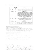
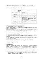
Bit Definitions - Status Byte Summary Register
Bit
Decimal
Value
Definition
0-2 not used
0
Always set to 0
3 QUES
8
One or more bits are set in the status
register.
4 MAV
16
Data is available in the power supply’s
output buffer.
5 ESB
32
One or more bits are stored in the
standard event register.
6 RQS
64
The power supply is requesting service
(serial poll).
7 not used
0
Always set to 0
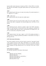
The status byte summary register is cleared when:
1. You execute the *CLS (clear status) command.
2. Querying the standard event register (*ESR? command) will clear only bit 5 in the
status byte summary register.
For example, if 24 (8 + 16) is returned when you query the status of the Status Byte
register, it is convinced that QUES and MAV conditions have occurred.
The status byte enable register (Request Service) is cleared when:
1. You execute the *SRE 0 command.
2. You turn on the power and have configured the power supply using the *PSC 1
command.
3. The enable register will not be cleared at power-on if you have configured the
power supply using *PSC 0.
For example, you must send *SRE 96 (32 + 64) to enable ESB and RQS bits.
Status Reporting Commands
SYSTem:ERRor?
This query command reads one error from the error queue. When the front-panel
ERROR annunciator turns on, one or more command syntax or hardware errors have
been detected. A record of up to 20 errors can be stored in the power supply’s error
queue. The additional errors will not be stored.
1.
Errors are stored and retrieved in first-in-first-out (FIFO) order. The first error
returned is the first error that was stored. When you have read all errors from the
queue, the “ERROR” annunciator turns off.

