28
Multifunction LCD Digital Timer
Safety Precautions
Caution
Do not use the product where corrosive or
volatile gases are present, or there may
occasionally be a risk of explosion.
Usable life of output relay is determined by
switch condition. According the actual usage,
use product within its rated load and electrical
life expectancy. If using product beyond its life
expectancy, its contacts may become fused or
there may be a risk of fire.
Do not disassemble, repair, or modify the
product. Doing so may result in electric shock,
fire, or malfunction.
Do not allow metal objects or conductive wires
to enter the product, which may result in electric
shock, fire, or malfunction.
Power Supplies
For the power supply of an input device, use an
isolating transformer with the primary and the
secondary winding not grounded.
Input terminals
Power supply
Circuit
Rectifie
Isolation transformer is requuired
Make sure that the voltage applied is within the
specified range, otherwise the internal elements of
Timer may be damaged.
Do not touch the input terminals while power is
supplied, and so touching the input terminals with
power supplied may result in electric shock.
When turning the power ON and OFF, input signal
reception is possible, unstable, or impossible.
Turn the power ON and OFF using a relay with a
rated capacity
of 0A minimum to prevent contact deterioration
due to inrush
current caused by turning the power ON and OFF.
Be sure that the power voltage can be immediately
reached to the supply voltage value by relays or
switches, otherwise it can not be reset or timing
error.
Power Failure Backup
All data is stored in the EEPROM when there is a
power failure. The EEPROM can be overwritten
more than 100,000 times.
Operating mode
Overwriting timing
A - 3 , F mode
When power is turned OFF
Other mode
When settings are changed
√
√
√
√
Input and Output
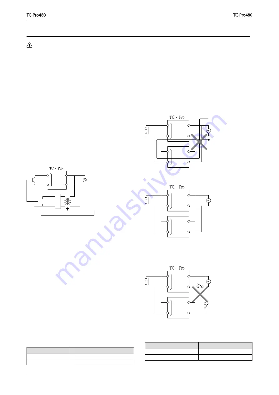
When connecting relay and transformer as an
external signal input device, it is necessary to pay
attention to the following points to prevent the short
circuit because of the hidden current flowing to the
power supply. If a relay or transistor connected to
two or more timers, those input terminals must be
connected correctly, otherwise it can cause short
circuit.
Incorrect
The contact or transistor as an external input signal
Input terminal
Input terminal
Power supply
Short circuit current
Correct
Input terminal
Input terminal
Power supply
Don’t connect the unattached power switch as
below, and without considering whether the timer is
different or not.
Input terminal
Input terminal
Power supply
Response time when resetting
The following table shows the delay from when the
reset signal is input until the output is turned OFF.
Min. reset signal width
Output delay time
ms
0.8~1.2ms
20ms
15~25ms
Summary of Contents for TC-Pro480 Series
Page 1: ...Ver 3 0...
Page 35: ...List of Models...


