background image

En

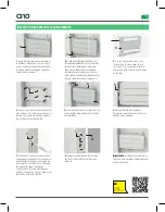
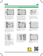
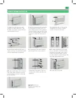
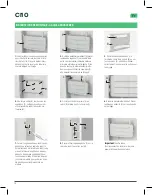
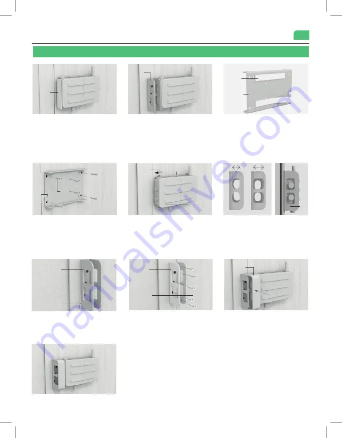
7. 

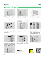
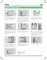
Repeat the drilling process to fi x the bolt 

storage part (E) to the door using the screws 

provided (M).

8. 

Press the trim (E1) into place.

Important: 

Check the lock 

functions correctly, always from 

inside the home.

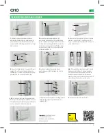
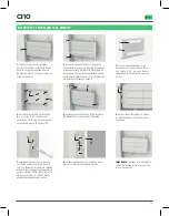
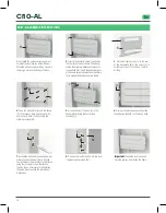
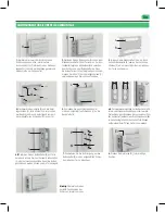
1. 

Calculate the position where you want to 

install the lock, always inside the door. Place 

the adhesive spacer (H) as shown in the image, 

stuck to the body of the lock.

2.

Next to the adhesive spacer (H), position the 

bolt storage part (E) on the door frame. The 

spacer marks the minimum distance between 

the lock and the bolt storage part. If both these 

parts are not at the same height, you must use 

the shims (C) to wedge the lock as shown in 

step 4.

3.

 Fix the adhesive strips (I) to the rear of the 

base plate (B) or the shims (C) to suitably 

position it on the door before drilling.

4.

 Once the base plate (B) and the shims (C), if 

necessary, have been pre-positioned, drill and fi x 

to the door using the screws provided (M).

5. 

Screw the body of the lock (A) to the base 

plate (B) using the four screws provided (L).

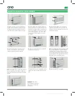
6.B 

Position the bolt storage part (E) on the door 

frame, fi xing it with an adhesive strip (I) at the 

correct height to ensure the lock can be closed 

and the door locked.

SURFACE ASSEMBLY INSTRUCTIONS

M

E

E

1

H

I

B

A

L

B

E

I

A

M

B

E

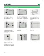
6_A. 

To adjust the bolts better, the (E) compo-

nent can be installed in two different positions. 

With the bolts in the closed position, verify in 

which position to install the piece. The bolts 

must stay as close as possible to the edge of (E) 

to avoid play when opening the door.

Summary of Contents for CI10

Page 1: ...rte con telecomando PT Ferrolho de seguran a invis vel para portas com comando distancia EN Invisible safety lock for doors with remote control FR Verrou de s curit invisible pour portes avec t l comm...

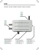
Page 2: ...ampa de alojamento das pilhas EN Battery storage cover FR Couvercle compartiment piles DE Batteriefachabdeckung ES Tornillo de alojamiento de pilas IT Vite del vano batteria PT Parafuso de alojamento...

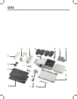
Page 3: ...D A B C E O E1 J P F K L M N G H I CI10...

Page 4: ......

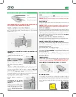
Page 5: ...adura Debe cambiar las pilas para garantizar un funcionamiento correcto APERTURA DE EMERGENCIA Encasodequelacerraduranofuncionealpulsarelbot nAdelmandoadistancia por pilas agotadas deberealizarseuna a...

Page 6: ...3 Fije las bandas adhesivas I en la trasera de la placa base B o en las calzas C y D para posicionarla adecuadamente sobre la puerta antes de taladrar I B A 4 Una vez pre colocada la placa base B y l...

Page 7: ...G en los bulones de la cerradura G 4 Una vez pre colocada la placa base B y las calzas C y D si fueran necesarias se taladra y se sujeta a la puerta mediante los tornillos suministrados M 5 Atornille...

Page 8: ...e sono scariche la serratura emette 5 segnali acustici al momento di essere aperta Le batterie devono essere sostituite per garantire il corretto funzionamento APERTURA DI EMERGENZA Se la serratura no...

Page 9: ...le strisce adesive I sul retro della piastra di supporto B o sugli spessori C e D per posizionarla correttamente sulla porta prima della foratura I B A 4 Una volta che la piastra di supporto B e gli s...

Page 10: ...osizionare i dischi adesivi G sui bulloni della serratura G 4 Una volta che la piastra di supporto B e gli spessori C e D sono stati posizionati se necessario si procede alla foratura e al ssaggio all...

Page 11: ...ir um funcionamento correto ABERTURA DE EMERG NCIA Caso a fechadura n o funcione ao pressionar o bot o A do comando dis t ncia no caso de pilhas gastas deve ser realizada uma abertura de emer g ncia n...

Page 12: ...pe as C e D para aplicar um cal o na fechadura no passo 4 E 3 Fixe as bandas adesivas I na parte posterior da placa base B ou nos cal os C e D para a posicionar adequadamente sobre a porta antes de f...

Page 13: ...loque os discos adesivos G nas trancas da fechadura G 4 Uma vez pr colocada a placa base B e os cal os C e D caso sejam necess rios perfura se e xa se porta usando os parafusos fornecidos M 5 Aparafus...

Page 14: ...press button A on the remote control Once open you will hear two beeps IMPORTANT When the batteries are about to run out the lock will beep ve times when opened The batteries must be changed to ensur...

Page 15: ...p 4 3 Fix the adhesive strips I to the rear of the base plate B or the shims C to suitably position it on the door before drilling 4 Once the base plate B and the shims C if necessary have been pre po...

Page 16: ...ve spacer Position the adhesive disks G on the lock s bolts 4 Once the base plate B and the shims C if necessary have been pre positio ned drill and x to the door using the screws provided M 5 Screw t...

Page 17: ...IMPORTANT Lorsque les piles sont court la serrure met 5 bips au moment de l ouverture Vous devez remplacer les piles pour assurer un bon fonctionne ment OUVERTURE D URGENCE Si la serrure ne fonctionne...

Page 18: ...serrure lors de l tape 4 3 Coller les bandes adh sives I l arri re du cadre de la serrure B ou sur les sous pans C a n de positionner correctement la serrure sur la porte avant le per age 4 Une fois l...

Page 19: ...adh sif Placer les disques adh sifs G sur les p nes de verrouillage 4 Une fois le cadre B et si besoins les sous pans C sont positionn s percer et xer le cadre la porte avec les vis fournies M 5 Visse...

Page 20: ...n fast leer sind gibt das Schloss vier Signalt ne ab und verriegeltnicht NORMALESENTRIEGELN Bet tigenSiedieTaste aufderFernbedienung umdasSchlosszuentriegeln Sobald dasSchlossentriegeltist ert nenzwei...

Page 21: ...legen 3 Bringen Sie die Klebestreifen I an der R ck seite der Basisplatte B oder an den Unterlegs cheiben C an um sie vor dem Bohren richtig an der T r zu positionieren 4 Nachdem die Basisplatte B und...

Page 22: ...ernen Sie den Klebeabstandhalter Legen Sie die Klebescheiben G auf die Schlossbolzen 4 Nachdem die Basisplatte B und die Unterlegscheiben C falls erforderlich vormontiert wurden bohren Sie und befesti...

Page 23: ...23...

Page 24: ...Seguridad S L declara que la Cerradura de Seguridad Invisible ref CI10 es conforme con la directiva 2014 53 UE DECLARACI N UE DE CONFORMIDAD SIMPLIFICADA SEG N LAS DIRECTIVAS 2014 53 EU EMC Y 2015 863...

Reviews: