background image

ARREL Audio 


CL-266 User Manual, Issue 0.1


Page 9 


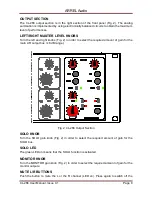
MUTE L/R function (LED off). 

MONO BUTTON 

Push the button to obtain a   mono output (LED on). Press again to switch off the MONO 
function (LED off). 

INSERT BY PASS BUTTONS 

Push the button to activate the insert points (1 and 2) (LED on). Press again to bypass the 
insert points (LED on). 

PHONES JACK 

This 

1/4” stereo TRS jack is for headphones with a minimum headphone impedance of 

600

Ω.


SEND/RETURN JACKS 

4 x 1/4” TRS jacks for insert 1 and 2 (send L-R, return L-R) 

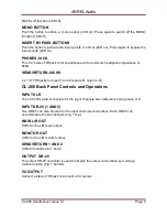
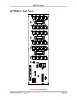
CL-266 Back Panel Controls and Operations 

INPUT XLR 

The 16 XLR female connectors for the input channels are clustered ion two groups of 8. 

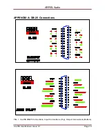
INPUT DB-25 (1 AND 2) 

Two DB-25 can also be used for the input channels connections. Each DB-25 can 
accommodate 8 input channels (Fig. 1 Top). 

MAIN L/R OUT 

XLRs for the L/R main output. 

MONITOR OUT 

XLRs for the L/R monitor output. 

SEND/RETURN 1 AND 2 

XLRs for send/return 1 and 2. 

OUTPUT  DB-25  

The output DB-25 connector is used to simplify the output connections by a using a 
multicore cable. (Fig. 1 bottom)  

VU OUTPUT 

Connect a stereo TRS jack to connect a VU system. 


Summary of Contents for CL-266 16

Page 1: ...CL 266 16 Channel Summing Mixer User Manual Issue 0 1...

Page 2: ...ctrical storms Do not place the instrument in an unstable position where it might accidentally fall over Before moving the instrument remove all connected cables When setting up the product make sure...

Page 3: ...stems and related documentation In any case we reserve the right to change the specifications without notice but in the respect to the current legislation Disclaimer The information contained in this...

Page 4: ...e button 7 Output section 8 Left RIGHT master LEVEL KNOBS 8 SOLO KNOB 8 SOLO LED 8 MONITOR KNOB 8 MUTE L R BUTTONS 8 MONO BUTTON 9 INSERT BY PASS BUTTONS 9 PHONES JACK 9 SEND RETURN JACKS 9 4 x 1 4 TR...

Page 5: ...r device The use of the send return front panel jacks automatically disables the corresponding rear panel connected device The send signal on the front panel jacks is always present allowing the set u...

Page 6: ...6 is contained in a 3U rack metal box No specific air conditioning is required for the racks provided that there is a free flow of air through the rack from front to back and the temperature is mainta...

Page 7: ...version available Fig 1 Fig 1 CL 266 Input Section INPUT SECTION PAN KNOB This is a 3 75 dB centre pan with S Law shaping to help accurate panning to extremes of left and right INPUT SECTION SOLO BUTT...

Page 8: ...nobs Fig 2 in order to select the required amount of gain for the main L R output bus 6 dB range Fig 2 CL 266 Output Section SOLO KNOB Turn the SOLO gain knob Fig 2 in order to select the required amo...

Page 9: ...RS jacks for insert 1 and 2 send L R return L R CL 266 Back Panel Controls and Operations INPUT XLR The 16 XLR female connectors for the input channels are clustered ion two groups of 8 INPUT DB 25 1...

Page 10: ...ARREL Audio CL 266 User Manual Issue 0 1 Page 10 APPENDIX A DB 25 Connections FIG 1 CL 266 DB 25 Connections Input Connections Top Output Connections Bottom...

Page 11: ...ARREL Audio CL 266 User Manual Issue 0 1 Page 11 APPENDIX B Front Panel FIG 3 CL 266 Front Panel...

Page 12: ...ARREL Audio CL 266 User Manual Issue 0 1 Page 12 APPENDIX C Back Panel Fig 4 CL 266 Back Panel...

Page 13: ...INSERT R Monitor Level Pot Solo Level Pot 2 mute buttons Mute L Mute R Mono button Front Panel Indicators Input Section each channel yellow LED Solo red LED Mute Master Section 2 green LEDs Insert L I...

Reviews: