86
Motion Control Interface MCI-1
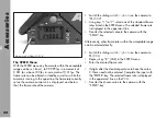
The MCI-1
➪
photo
is attached to the 26pin connector
on the lower right side of the camera and secured with a
screw
➪
photo
to the handgrip mount (use a 3mm allen
key). It adds the motion control modes to the camera and
splits the 26pin connector in two differently coded 12pin
Fischer connectors for the capping shutter and the interface
for external motion control computer.
• The MC socket
➪
photo
is for the motion control computer.
• The ICS socket
➪
photo
is for the capping shutter.
The capping shutter has to be fitted with a 12pin Fischer
socket and the K-MCI-ICS K2.52147.0 has to be used.
ATENTION: switch off power and disconnect
battery cable before installing the MCI-1 and
attaching cables to the MC and ICS socket.
Accessories
fastening screw
MC-socket
ICS-socket
Summary of Contents for Arriflex 435 Advanced
Page 8: ...8 Contents...
Page 12: ...12 Installation magazine opening cover movement in locked position loop protector...
Page 18: ...18 Installation shoulder set S 4 shoulder cushion base plate...
Page 26: ...26 Magazines...
Page 54: ...54 Optics...
Page 78: ...78 Accessories...
Page 100: ...100 Accessories...
Page 130: ...130 Maintenance...
Page 137: ...137 Appendix...
Page 138: ...138 Appendix...
Page 144: ...144 Index...
Page 156: ...Technical data are subject to change without notice Printed in Germany Ident Nr 5 58231 0...


