background image


ARRIFLEX D‑21

INSTRUCTION MANUAL

November 2009

COPYRIGHT © 2009 ARNOLD & RICHTER CINE TECHNIK GMBH & CO BETRIEBS KG. ALL RIGHTS RESERVED.

NO PART OF THIS DOCUMENT MAY BE USED FOR DISTRIBUTION, REPRODUCTION, TRANSMISSION, 
TRANSCRIPTION, STORAGE IN A DATA RETRIEVAL SYSTEM, OR TRANSLATED INTO ANY LANGUAGE 

IN ANY FORM BY ANY MEANS WITHOUT THE PRIOR WRITTEN CONSENT OF ARRI.

IF YOU ARE DOWNLOADING FILES FROM OUR WEB PAGES FOR YOUR PERSONAL USE, MAKE 

SURE TO CHECK FOR UPDATED VERSIONS. ARRI CANNOT TAKE ANY LIABILITY WHATSOEVER FOR 

DOWNLOADED FILES, AS TECHNICAL DATA ARE SUBJECT TO CHANGE WITHOUT NOTICE.

Summary of Contents for ARRIFLEX D-21

Page 1: ...TION TRANSMISSION TRANSCRIPTION STORAGE IN A DATA RETRIEVAL SYSTEM OR TRANSLATED INTO ANY LANGUAGE IN ANY FORM BY ANY MEANS WITHOUT THE PRIOR WRITTEN CONSENT OF ARRI IF YOU ARE DOWNLOADING FILES FROM OUR WEB PAGES FOR YOUR PERSONAL USE MAKE SURE TO CHECK FOR UPDATED VERSIONS ARRI CANNOT TAKE ANY LIABILITY WHATSOEVER FOR DOWNLOADED FILES AS TECHNICAL DATA ARE SUBJECT TO CHANGE WITHOUT NOTICE ...

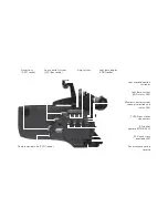
Page 2: ...Eyepiece lock LOCK switch NORM PS CCU switch PROG button MODE button Eyepiece focus adjustment Accessory mounting rosette Eyecup SEL button SET button PHASE button RUN button Operation control LED ...

Page 3: ...Image rotation release PL mount Ground glass Main camera switch Image rotation knob Tape hook Viewfinder arm friction adjustment Viewfinder arm Viewfinder extension lock ...

Page 4: ...election and status LED RS socket remote RUN 24 V 24 V accessory overload LED Accessory mounting rosette CLM 2 lens motor connectors Lens control system LCS bus socket Lens data display LDD socket Accessory ACC socket Camera control unit CCU socket Lens motor direction switches ...

Page 5: ...er supply BAT socket S Video Y C SD output Composite video SD output 3 8 16 mounting holes camera base Camera control unit CCU socket Accessory ACC socket 11 pin accessory socket 12 V and overload LED Lens control system LCS bus socket HD clock pulse output Grip system Tape hook Spirit level Viewfinder swivel release ...

Page 6: ...ion 15 4 Disclaimer 16 5 General Description 18 Product Identification 18 Scope 19 6 Power Supply 20 6 1 Mains Unit NG 12 26 R 20 6 2 CINE VCLX 2 Charger 21 6 3 CINE VCLX 2 Charger 21 6 4 Main Camera Switch 22 6 5 Accessory Power Supply 23 12 V Accessories 23 24 V Accessories 24 Overload Display 24 7 Installation of the Camera 25 7 1 Minimal Equipment Required for Operation 25 Contents 1 D 21 Left...

Page 7: ...29 Removing the Grip System 29 8 Optics 30 8 1 Lenses 30 Lens Mount 30 Lens Mount Position 30 Changing Lenses 30 8 2 Viewfinder System 31 Viewfinder Arm 33 Image Orientation 34 Removing the Viewfinder System 35 Universal Finder Arm 36 8 3 Ground Glasses 37 Exchanging the Ground Glass 37 8 4 ARRIGLOW 38 Exchanging the ARRIGLOW Mask 38 9 Camera Output Configuration 40 9 1 Output Interfaces 40 9 2 Vi...

Page 8: ...istics 54 SD Mode 59 Diagnostics 61 9 4 OSD Tools 64 10 Signal Connections 65 10 1 Signal Monitoring 65 10 2 Signal Wiring Instructions 65 HD422 Setup Standard Mode 66 HD422 High Speed Setup Standard Mode 67 HD444 Setup Standard Mode 68 Mscope HD422 Setup Standard Mode 69 Data Mode ARRIRAW Setup Advanced Mode 70 11 Camera Operation 71 11 1 Running and Stopping the Camera 71 11 2 Camera Display Mod...

Page 9: ...83 Enabling Disabling the Mirror Shutter Mode 4 84 Setting the Mirror Shutter Angle Mode 5 85 12 Recording 86 12 1 Recording Format Setup 86 12 2 Starting and Stopping the Recording 86 Recording Devices with Variable Frame Rate VariFrame Support 87 Recording Devices without Variable Frame Rate VariFrame Support 87 13 Functional Expansion Module FEM 2 88 13 1 Lens Data System 89 13 2 Wireless Syste...

Page 10: ...te Run Switch RS 4 104 14 7 RS Socket Distributor 24 V Plug on Module 105 14 8 Shoulder Set S 5 106 14 9 Fiber Link Unit FLU 1 107 Fiber Link Remote FLR 1 107 14 10 Wireless Remote Control WRC 2 110 14 11 Work Light 111 14 12 General Note 111 15 Camera Care 112 15 1 General Information 112 15 2 Imager Check 112 Imager Surface 112 Dust Check 113 Cleaning the Sensor Cover Glass 114 Condensation 116 ...

Page 11: ...ing 130 Data Mode 131 Dead Defective Pixels 133 HD Mode 133 Mscope 134 Scanning Methods p i PsF 135 Pixel Failure 136 17 3 Image Artifacts 138 Aliasing 138 Clipping 138 Dark Spots 138 Dead Defective Pixels 138 Horizontal Smear 139 Noise 139 Pixel Failure 139 Speckled Images 139 18 Index 140 19 ARRI Group Addresses 148 ...

Page 12: ...low these instructions to ensure against injury to yourself and damage to the system or other objects This safety information is in addition to the product specific operating instructions in general and must be strictly observed for safety reasons Read and understand all safety and operating instructions before you operate or install the system Retain all safety and operating instructions for futu...

Page 13: ...ny part of the system or before making any changes to the system especially the attaching or removing of cables Do not use solvents to clean Do not remove any screws that have been secured with paint Never run the camera without a lens or a protective cap in the lens mount receptacle Attention Danger of injury Never place your hand in the lens mount receptacle or the inside of the camera while it ...

Page 14: ...DIRECT SUNLIGHT VERY BRIGHT LIGHT SOURCES OR HIGH ENERGY LIGHT SOURCES e g laser beams This may lead to severe injury of your eyes or loss of sight and may cause permanent damage to the camera sensor 3 General Precautions 3 1 Storage and Transport To prevent damage to the mirror shutter and the sensor a protective cap must be on the lens mount receptacle while no lens is attached All cables have t...

Page 15: ...to the PL Mount of the camera when the camera is stored Note The air drying cartridge must be removed while the camera is transported or stored inside a transport case If camera needs to be stored in a place that is considerably cooler than the location where it will be used consider keeping the camera powered not running from a mains unit in addition to using the air drying cartridge In ambient t...

Page 16: ...y for any errors that may appear in this document The information is subject to change without notice For product specification changes since this manual was published refer to the latest publications of ARRI data sheets or data books etc for the most up to date specifications Not all products and or types are available in every country Please check with an ARRI sales representative for availabili...

Page 17: ...l theory In the case one or all of the foregoing clauses are not allowed by applicable law the fullest extent permissible clauses by applicable law are validated ARRI is a registered trademark of Arnold Richter Cine Technik GmbH Co Betriebs KG Note This product and the accessories recommended by the manufacturer fulfill the specifications of the EU Guideline 89 336 EWG ...

Page 18: ...al technology with film camera features that have been refined over ARRI s 90 year history It allows directors and cinematographers to shoot in the same way as they would with 35 mm film while taking advantage of the immediacy and economy of digital acquisition As the top of the line digital cameras from ARRI the market leader in professional imaging it is equipped with a number of unique features...

Page 19: ...plies to the following ARRIFLEX D 21 software and firmware versions Camera software packet 1 16 CRC 2be9f Color management version R2 20 E cover software version 2 03 E cover firmware version 1 09 Different software versions can result in different behavior ...

Page 20: ...electronic accessories with high power consumption First check that the correct mains voltage is set on the mains unit fuse on back of unit Connect the mains unit to AC mains power Ensure that the camera power is turned off Set the voltage switch on the mains unit to 26 V Plug the battery cable KC 20S or KC 29S spiral cable into the power supply socket on the camera and into the 26 V socket on the...

Page 21: ...tion Do not attempt to charge this battery with any other than the CINE VCLX 2 charger or other models specified by Anton Bauer CINE VCLX 2 Charger 6 3 Connect the charger to AC mains power Plug the charger cable into the charge input socket of the battery Once charged batteries may be kept on the charger until required Note For more information on CINE VCLX 2 battery and charger please check the ...

Page 22: ...aging status LEDs on the rear of the camera image light up red and the camera display shows the busy indicator When the camera is ready for operation the operation control LED turns off and the imaging status LEDs light up green Do not operate the camera before all three imaging status LEDs light up green Using any of the camera s buttons before it is ready for operation may cause faulty behavior ...

Page 23: ...e When the camera is powered from mains and a 12 V onboard monitor is powered from the camera running a video connection between this monitor and another device that is also powered from mains is likely to cause a ground loop The Isolating Power Adaptor IPA 1 see chapter 14 Accessories provides a 12 V isolated output from the camera to avoid ground loops Note The 11 pin accessory socket can only b...

Page 24: ... In this case the maximum allowable continuous current is 2 A Ensure that the accessories to be used are suited for the available voltage Overload Display If the current drawn at the accessory sockets exceeds the allowable maximum a self resetting safety circuit interrupts the power supply and a red warning LED lights up image If this happens turn the camera off unplug all accessories from the cam...

Page 25: ...ration are provided in the following chapters 7 2 Tripod and Remote Heads Tripod heads and remote heads used with the ARRIFLEX D 21 have to provide enough load capacity to support the camera and attached accessories The table to the right shows the camera weight for different components Note Check for the payload of remote heads and cranes In applications where the camera mount is subject to high ...

Page 26: ...ting of accessories BP 8 is designed for 19 mm support rods BP 9 is designed for 15 mm support rods The bridge plate sets consist of the base plate bridge plate and a pair of 440 mm support rods 19 mm support rods with lengths of 165 185 240 340 and 440 mm or 15 mm diameter support rods with lengths of 340 and 440 mm are available separately as options Note The bridge plate has to be adjusted to S...

Page 27: ...bly The camera s position can then be fixed with the clamping lever image Slide the support rods into the guides and clamp Equip the camera with the required accessories to determine the center of gravity Loosen the clamping lever and by sliding the camera on the base plate find the optimal balance position Then retighten the clamping lever Removing the Camera from the Tripod Before removing the c...

Page 28: ... support rods from the front Fit the appropriate support ring image loosely onto the lens Do not tighten Then slide the lens into the lens mount receptacle and lock It is essential that you take the weight of the lens mount until the lens support column of the support ring can rest on the lens support Move the LS 9 10 lens support so it is located under the support column of the lens support ring ...

Page 29: ...into the grip system Pull tight to enable the safety mechanism which prevents loosening Version with registering pins Place the hand grip on the grip system so the registering pins are inserted into the provided holes Using a 5 mm Allen key tighten the hand grip to the grip system with the 3 8 threaded bolt Removing the Grip System In order to minimize camera height the entire grip system can be r...

Page 30: ...s calibrated through the lens motor CLM 2 position which is then stored into accessories such as the Lens Data Archive LDA or the Wireless Remote Control WRC 2 Lens Mount Position The lens mount should always remain in Super 35 position 2 image although it is possible to rotate the lens mount to Normal 35 configuration 1 Unlike with 35 mm cameras this also applies when anamorphic lenses are used C...

Page 31: ...ciple of the camera s optical module delivers outstanding images with a cinematic look and feel but also makes the imager sensitive to contamination Dust particles that have settled on the sensor cover glass during a lens change may become visible as dark spots in the output image similar to lint leaving marks on exposed film The degree of this effect depends on the aperture of the lens 8 2 Viewfi...

Page 32: ...d with the other turn the knurled ring image in the OPEN direction until it unscrews from the eyepiece Remove the eyepiece Attaching the Eyepiece With the knurled ring in OPEN position place the eyepiece on the viewfinder Turn the knurled ring towards the LOCK position Check that the eyepiece is correctly seated Diopter Compensation The diopter compensation is fitted with a scale of 1 to 12 Positi...

Page 33: ...inder arm locks into the horizontal position The viewfinder arm friction can be altered if necessary by turning the Allen screw image To adjust the viewfinder arm release the locking mechanism by pressing the swivel release image Turn the viewfinder arm to the desired position Extending the Viewfinder Arm The viewfinder arm can be extended continuously by approx 50 mm 2 inches Turn the extension l...

Page 34: ...position Reactivating Image Orientation Turn the adjustment knob image until this locks in position Do not press the locking key Note The automatic image orientation mechanism locks in two positions 180 apart Pivoting the Contrast Filter To achieve a temporary subjective reduction of viewfinder contrast a contrast filter ND 6 can be pivoted into the optical beam path by means of a lever image The ...

Page 35: ...xed on a pivoting head to provide a secure working environment Loosen the three fastening screws using a 3 mm Allen key image Pull the viewfinder system up and off the camera Removing the viewfinder system exposes optical surfaces on both camera and viewfinder Do not touch the cover glasses Never operate the camera with an open viewfinder interface Attaching the Viewfinder System Place the viewfin...

Page 36: ... AVF 1 universal finder arm image which allows de squeezed viewing of the ground glass image This viewfinder arm can also be switched over to check the anamorphically squeezed image or for use with a spherical lens The universal finder arm can be fitted in place of the standard viewfinder arm by a service center or in a rental house To switch the viewfinder image to spherical or de squeezed anamor...

Page 37: ...t image in postproduction Exchanging the Ground Glass If the mirror shutter is not positioned in front of the sensor briefly press the PHASE button in standby so the sensor cover glass is protected by the shutter Turn the camera off and disconnect it from the power supply Remove the lens or the protective cap Using the special forceps Hirschmann clamp from the camera s toolkit pull the ground glas...

Page 38: ...ise as far as it will go Exchanging the ARRIGLOW Mask Each of the ground glasses available for the D 21 should be used together with a matching glow mask For a list of available formats please check the D 21 price list To exchange the glow mask Remove the viewfinder system as explained above Turn the viewfinder upside down and put it on a clean surface that is covered with foam material or clean l...

Page 39: ...refully push the glow mask into the holder with the slanted edge facing towards the rear end of the viewfinder system image without tilting it in the holder s guides Make sure the glow mask is inserted completely Close and lock the glow mask door by gently turning the locking screw 90 clockwise Attach the viewfinder system Turn on the ARRIGLOW and check that ground glass and glow mask are correctl...

Page 40: ...nu Most operational parameters for the ARRIFLEX D 21 are set using a video menu The video menu is shown as an on screen display on all SD video outputs Note Configuration of the camera outputs requires an SD monitor to be connected to one of the composite video outputs or the S Video output Note Additional functions including mirror shutter angle and programmable frame rates are controlled using t...

Page 41: ...readout operates at full sensor aperture with 1 33 1 4 3 aspect ratio up to a standard frame rate of 25 fps For frame rates of 29 97 or higher readout operates at a reduced height with 1 78 1 16 9 aspect ratio while retaining the full sensor aperture width The camera image in the SD video output therefore shows a 4 3 image up to 25 fps and a 16 9 letterbox display for 29 97 fps and above Note The ...

Page 42: ...ional options for settings that are automatically set in Standard Mode and enables the options for Data Mode ARRIRAW output and the use of log output characteristics for HD Mode Note Faulty configuration in Advanced Mode can affect image quality of the camera output User Mode Standard White Balance 3200 K Framerate 25PsF HD SDI Mode HD422 Output Range Normal Range Contrast Char EI 200 SD Mode Diag...

Page 43: ... to select the first number Briefly press the video menu button to enter this number Access select and enter the remaining digits zeros can be skipped Confirm switching to Advanced Mode using OK Note If the wrong code is entered user mode switching is cancelled Note When switching from advanced to Standard Mode custom settings made in Advanced Mode will be reset to Standard Mode defaults HD SDI 2 ...

Page 44: ...0 K or a previously saved automatic or manual white balance setting WB 1 3 Automatic White Balance To perform an automatic white balance If the camera is not running briefly press the RUN button Point the camera at a homogeneously lit neutral grey surface Using a waveform monitor or the RGB or LUM Histogram see OSD Tools adjust iris or lighting so the output video level lies within 40 to 70 Enter ...

Page 45: ...balance setting is automatically applied Note If the camera is not running the OSD will show Image not available Note If it is not possible to calculate a color temperature from the processed white balance values the menu will show CCT out of range These values can be saved used and will not produce out of gamut errors but no color temperature can be given Note Automatic white balance settings sho...

Page 46: ...value for the blue channel gain Use Save Settings Select and confirm a slot WB 1 3 to save the manual white balance setting When saved the white balance setting is automatically applied Note The initial values for R G and B are based on the previously used white balance setting Note Manual white balance settings should be checked with a waveform monitor in RGB waveform parade mode or vector scope ...

Page 47: ...he camera to a programmed variable frame rate First set the required standard system frame rate according to the instructions above then set a custom speed using electronic accessories or the PS Mode as described in chapter 11 Camera Operation Note The standard frame rate set here determines the maximum frame rate selectable for programmable variable speeds Note The range of standard frame rates a...

Page 48: ... adjust parameters that need to be customized for the second output HD SDI 2 and or SD To select the output board to be configured Enter Output Board image Select and confirm ALL 1 2 SD HD SDI 1 HD SDI 2 or SD Note Using ALL 1 2 SD assigns the subsequent settings made for HD SDI mode output range color matrix and contrast characteristic to all output boards and as far as applicable to the SD outpu...

Page 49: ...mple image shows the setup for output board HD SDI 1 HD SDI 2 is set to a different HD SDI mode and output range Both settings do not apply for the SD output The settings for color matrix and contrast characteristics are the same for all outputs Symbol Meaning 1 Setting applies to HD SDI 1 2 Setting applies to HD SDI 2 S Setting applies to SD output Setting does not apply to HD SDI 1 HD SDI 2 or S...

Page 50: ... to Extended output range before re apply this setting Note Selecting ARRIRAW here switches to Data Mode which disables the options for output range color matrix and contrast characteristic as these adjustments are not applied for this output mode Note When using ARRIRAW for recording and HD output for preview it is recommended to set HD SDI 1 to an HD Mode HD444 HD422 or Mscope and HD SDI 2 to AR...

Page 51: ... normal extended normal extended normal extended normal extended Standard frame rates 23 976 24 25 29 97 30 23 976 24 25 29 97 30 23 976 24 25 29 97 30 48 50 59 94 60 23 976 24 25 Available fps range 1 25 1 30 1 30 1 30 1 60 1 25 Note Data Mode ARRIRAW requires an ARRIRAW T Link certified recorder or a system capable of recording uncompressed SMPTE 372M compliant RGBA HD SDI signals For more infor...

Page 52: ...from the list Note Changing the output range using Output Board ALL 1 2 SD will change the output range for both HD SDI output boards simultaneously Note Output range is automatically set to Normal Range in Standard Mode Note Normal range output is commonly used for shooting a broadcast ready 4 2 2 production Note Using ARRIRAW as HD SDI mode for an output disables this parameter Note Changing the...

Page 53: ...his matrix is based on film densities to provide a color rendition that closely matches negative stock and is recommended in combination with the logarithmic characteristic setups see below To set the color matrix for the selected output board Enter Color Matrix image Select and confirm a color matrix from the list Note The camera does not offer optimized color matrix settings for automatic or man...

Page 54: ...s The ARRIFLEX D 21 offers two types of characteristic curves Exposure Index EI characteristic curves intended for direct visually correct HD output Log Characteristic curves intended for use in DI or Filmstream oriented workflows To set the contrast characteristic curve for the selected output board Enter Contrast Char image Select and confirm one of the contrast characteristics from the list Not...

Page 55: ...uctions EI Sensitivity and Dynamic Range Distribution Please note that working with different EI values is different from the traditional film exposure paradigm Film stock of different sensitivity maintains its overall dynamic range distribution Changing EI characteristic curves influences the dynamic range distribution A higher EI value allows the sensor to be exposed with less light As a result ...

Page 56: ...tio of about 70 above and 30 below at EI 800 and about 40 above and 60 below at EI 100 Note The contrast characteristics shown here are for illustration only and may differ from the actual curves supplied with the color management software version installed in your camera Recommended EI Setup HD SDI Mode HD422 or HD444 Output Range according to HD SDI mode Color Matrix according to white balance 0...

Page 57: ...tonal balance of the signal has to be adjusted using LUTs or through color correction Recommended Log C Setup HD SDI Mode HD444 up to 30PsF Output Range Extended Range Color Matrix LOG Note When using Log C the correct lens aperture should be determined using an exposure meter On a waveform display a correctly exposed image is offset in the blacks and does not reach the maximum signal level due to...

Page 58: ... Log C the correct lens aperture should be determined using an exposure meter On a waveform display the mid tones of a correctly exposed image will be offset and highlights will not reach the maximum signal level due to the given specifications Note To correctly preview the material on an HD monitor a Filmstream lin conversion LUT optionally also adjusting the EI has to be applied on the signal As...

Page 59: ...tput Zebra image Use High and or Low Zebra to activate or deactivate the function Use High and or Low Zebra Level to enter the threshold video levels Use High and or Low Zebra Color to change the zebra pattern color Use Exit to quit the output zebra setup Note High and low zebra operate independently and remain active above the set thresholds It is not possible to set the zebra to be active only b...

Page 60: ...nter crop 4 3 frame within the 16 9 image To select an aspect ratio for the format marking Enter SD Mode Format Marking image Select and confirm an aspect ratio from the list Use Exit to quit the format marking setup To setup and store a custom format marking Enter SD Mode Format Marking Enter Edit Format Adjust the left border of the format marking and confirm Repeat adjustment for right upper an...

Page 61: ...CM Status 3 image displays internal temperature and voltage readings Note The Diagnostics menus should always be exited before a recording is started Camera Status RUN Shutter Mode ROTATING Shutter Pos ROTATING Shutter Angle 180 00 Image Size 2880x2160 Framerate 25 000 fps CDS ON Mode HD SDI 1 HD422 Mode HD SDI 2 HD422 Next Exit Status 1 ECU OK SENSOR OK ADGOC0 OK ADGOC1 OK ADGOC2 OK ADGOC3 OK PIM...

Page 62: ...rature at nominal level Off Slight sensor temperature deviation from nominal level Turn camera off and wait 5 minutes before turning it back on Make sure that air can flow through the ventilation shafts at the back of the camera body Red Sensor temperature deviation from nominal level above acceptable limit Possible malfunction of internal cooling system Turn camera off and wait 5 minutes before t...

Page 63: ...ostics Standard Reset Confirm the standard reset by entering Yes or cancel by entering No When the power LED on the camera backside starts blinking red restart the camera using the main power switch to complete the standard reset The camera will return to the user mode it was set to when the standard reset was performed After a standard reset the camera will default to these settings White Balance...

Page 64: ...inder output zebra an RGB histogram separate R G B and LUMINANCE histograms To access the OSD Tools Exit the video menu if it is displayed Rotate the menu button to step through the tools Note The viewfinder output zebra is setup using the video menu See section SD Mode Note The histogram always refers to the settings of the SD output 1 78 1 Viewfinder Zebra RGB Histogram ...

Page 65: ...m length for reliable a connection depends on quality and condition of the cable in use To provide more security in case of minor defects the length stated here is intentionally shorter than what is commonly specified by cable manufacturers Signal Monitoring 10 1 General recommendations Always verify that all recordings are free of defects All recording setups should include a control monitor to a...

Page 66: ...stem input format to 4 2 2 YCbCr 1080PsF i using the frame rate set on the camera Connect camera output HD SDI 1 or 2 link A to recording input HD SDI IN A Connect recording output HD SDI OUT A or HD SDI monitor out to control monitor input HD SDI IN A or B Note When set to HD422 the camera output boards transmit the same signal on link A and B Using link A is recommended Note Standard Mode setup ...

Page 67: ...output above 30PsF using dual stream signals is not supported by all recording systems Depending on the recording system live monitoring of these signals may not be possible or restricted to output of every other frame For more information on HD422 dual stream output and recording system requirements see the glossary in chapter 17 Appendix Note Dual stream dual camera recording is commonly used fo...

Page 68: ...ards set to HD444 require link A and B for signal output Always use link A and B from the same output board Note Standard Mode setup assigns the same settings to all HD SDI output boards Individual configuration of the output boards requires Advanced Mode setup Note If the control monitor supports 4 4 4 signals recording outputs HD SDI OUT A and B can also be connected to the control monitor input...

Page 69: ...ards requires Advanced Mode setup Note Mscope is intended for use with anamorphic lenses The full sensor area with a 4 3 aspect ratio is output as a 1920 x 1440 image using a dual stream signal Each link contains 1920 x 720 lines of the frame A display connected to one camera link or the recorder s monitor OUT will display a de squeezed preview image Note Dual stream dual camera recording is commo...

Page 70: ...d Mode The second HD SDI output board can be set to any HD mode up to 30PsF or Mscope for frame rates up to 25PsF Note ARRIRAW Data Mode output can be recorded using ARRIRAW T Link certified recorders or other systems supporting RGBA HD SDI streams according to SMPTE 372M Recorders without ARRIRAW T Link certificate may offer limited or no preview output Please refer to the recording system s user...

Page 71: ...ra backside image light up green Using any of the camera s buttons before it is ready for operation may cause faulty behavior When the camera is in standby it outputs a black image or a still frame To start or stop the camera Briefly press the RUN button The operation control LED glows red when the mirror shutter starts or stops spinning Once the set frame rate has been reached the operation contr...

Page 72: ...formation on checking the imager can be found in chapter 15 Camera Care Note Unless stated otherwise operational parameters cannot be changed while the mirror shutter is running 11 2 Camera Display Modes The camera display at the front left side of the camera image is used to display adjust parameters connected with the imager s exposure Access to these parameters is provided through different dis...

Page 73: ...rame rate if a program is active Change programmed frame rate Mode 3 Total take frame counter Power supply voltage V Toggle 1st display line for mode 1 and mode 3 set low battery warning level Lobat Mode 4 6 Async signal enabled or disabled _ at camera run stop and volume of the acoustic warning signal Rotating shutter enabled or disabled _ Async signal enable disable volume or warning signal rota...

Page 74: ...nected but no sync frequency is available PROG continuous The stored program is activated and can be started while the camera is running by pressing the PROG button blinking The activated program cannot be run with the set values Out of range fps or shutter or battery voltage too low blinking The symbol blinks and the operation control LED glows red The electronic shutter adjustment is defective _...

Page 75: ...tentional operation of SEL SET PROG and the Video Menu button Note If SEL SET or PROG is pressed while the camera is locked the display will show OFF Note that the LOCK switch also disables the video menu functions on the back of the camera Locking the camera display has no influence on the phase function the NORM PS CCU switch and on electronic accessories Shutter Angle Measurement Holding the PH...

Page 76: ...cedure for Changing Frame Rates First set a standard frame rate using the video menu see chapter 9 Camera Output Configuration Next set a programmed frame rate using the camera display see below or an electronic accessory or program a ramp using an electronic accessory Note The maximum frame rate selectable for programmable speeds and ramps is determined by the standard frame rate set in the video...

Page 77: ...s stored even if the camera is not switched on at the main switch This battery has a lifetime of approx 10 years If the programmed frame rate is not available when the camera is switched on again the buffer battery has to be replaced by an ARRI service center Shifting Phase To capture quartz synchronized monitors hold the PHASE button pressed after the camera has run up until the horizontal bar is...

Page 78: ...the camera is running creates a basic speed ramp This operation does not allow automated exposure compensation Fine Tuning the Programmed Frame Rate PS Mode Note See General Procedure for Changing Frame Rates Fine tuning of the programmed frame rate can be carried out while the camera is running by means of the buttons SEL slower and SET faster The setting can be adjusted in increments of 0 001 fp...

Page 79: ...output top connector on one of the output boards and then routed back into both camera s ACC socket using a special cable This method allows synchronizing the cameras to standard frame rates between 23 976 and 30 fps Note Using this method does not allow adjusting the shutter phase Note This method requires a special cable which is available from ARRI on request Synchronizing using the ESU 1 The s...

Page 80: ...herefore cannot be used as shot metadata Two different frame counter types are shown on the camera display in mode 3 and optionally mode 1 image The total amount of exposed frames The take length amount of frames used in an individual take Note A t in the first digit of the upper display line indicates the display of take length frames ...

Page 81: ...nter Configuration Mode 3 To exchange the frame counter type displayed in modes 1 and 3 Change from mode 1 to mode 3 by pressing the MODE button twice Press the SEL button the first digit in the upper display line blinks Within three seconds press the SET button The currently set counting value of mode 3 is displayed The corresponding counting value optionally shown in mode 1 is automatically alte...

Page 82: ...tton twice Press SEL twice to change to the voltage level setting Press the SET button repeatedly until the desired value is reached values below 20 V cannot be set Repeat this procedure until all digits are set to the desired values A final confirmation is not necessary Note For NiCd batteries the voltage level should be set to approximately 22 23 V For Li ion batteries a higher value of approxim...

Page 83: ...our settings shown in the table below Note Mode 4 actually is Mode 6 based on the ARRI camera display reference structure Electronic accessories therefore identify it as Mode 6 Display Warning signal on start Warning signal on stop LS _ _ off off LS _ on off LS _ off on LS on on Setting the Volume of the Warning Signal Change from mode 1 to mode 4 by pressing the MODE button three times Press the ...

Page 84: ...er readout Note At speeds above 29 97 fps the sensor readout switches from 2880 x 2160 to 2880 x 1620 As a readout of less pixels takes less time this switch causes a step in the corresponding shutter angle as can be seen in the table to the right Note When the mirror shutter is enabled it controls the sensor s exposure while the electronic shutter is synchronized for readout in the dark phase Whe...

Page 85: ...he range of 11 2 180 The procedure is described in the respective instruction manual Note Mode 5 actually is Mode 7 based on the ARRI camera display reference structure Electronic accessories therefore identify it as Mode 7 Filming with HMI Light When shooting scenes with non electronic ballast HMI or fluorescent lighting the pulsing light intensity depends on the supply frequency To achieve const...

Page 86: ...HD422 outputs two 1080PsF i 4 2 2 YCbCr signals via dual stream HD SDI according to SMPTE 372M ARRIRAW outputs a 2880x2160 or 2880x1620p RAW 12 bit stream mapped into a 4 4 4 4 RGBA signal via dual link HD SDI according to SMPTE 372M ARRIRAW T Link Note Please refer to the recording system s user manual for instructions on the recording format setup Note Also see chapters 9 Camera Output Configura...

Page 87: ...nnections and 17 Appendix Glossary To display a live camera image on the set monitors without recording the signal Take the recording device out of record standby mode Put the recording device into EE mode if this does not happen automatically Note Please refer to the recording system s user manual for detailed instructions Recording Devices without Variable Frame Rate VariFrame Support Run the ca...

Page 88: ...motors WHA 2 WHA 3 and ZMU 3 LDD Lens Data Display interface ACC interface for ESU 1 CCU interface RS 232 for connection of electronic accessories such as WRC 2 or the Cine Tape Measure System URM port for optional URM 3 to enable wireless lens and camera control LDD socket Lens motor status LED CLM 2 direction switch LCS bus sockets ACC socket CCU socket Battery compartment URM port Channel selec...

Page 89: ...figuration Together with external distance measuring devices UMT 1 or Cine Tape Measure it also allows focus tracking The LDS is compatible with all lenses equipped with ARRI LDS contacts and lenses using compatible protocols The LDS status is indicated by the LDS status LED image Lens data displays are connected to the LDD socket image on top of the FEM 2 module To connect an LDD use LDD cable K4...

Page 90: ...ss communication of positioning information for lenses and remote control of camera functions Switch off the camera and disconnect all cables from the camera and FEM 2 before installing the URM 3 The installation of the URM 3 has to be carried out on a static free workstation Using a 2 5 mm Allen key loosen the two screws of the URM port cover Remove the two screws from the holes in the cover Appl...

Page 91: ...even and the other to an odd channel Regional radio guidelines must be observed Do not use RF channels that are not permitted in your country Channel Frequency Use 0 2444 2472 MHz Europe except France and Spain To be used in the USA Canada Mexico New Zealand 1 2406 2345 MHz Europe except France and Spain To be used in the USA Canada Mexico New Zealand 2 2444 2472 MHz Europe except Spain 3 2406 234...

Page 92: ...LED Status Off Wireless remote control deactivated channel 9 or camera deactivated or camera without power Red green alternating Radio modem initialization in progress Do not activate wireless main until ready Green blinking Wireless remote control is ready Activate wireless main unit Green Wireless remote control OK Red Channel selection has been changed while system was active Turn the camera of...

Page 93: ...a CLM 1 motor is set to the function zoom focus or iris and is connected to the FEM 2 the corresponding CLM 2 connection is deactivated Each CLM 2 motor connection has a status LED and a direction switch image CLM 2 Status Indications The status for each CLM 2 motor is displayed by its own status LED see table Note More information on LCS and WRS setups can be found in the FEM 2 instruction manual...

Page 94: ...camera control unit can be used to control the ARRIFLEX D 21 while more than one WMU 3 can be used in parallel to control lens functions Note More information on LCS and WRS setups can be found in the FEM 2 instruction manual Note For details on how to use the WRC 2 please see the instruction manual supplied with this unit The image to the right shows a wired remote control setup with the WRC 2 co...

Page 95: ...ncompatible accessories or accessories not approved by ARRI could damage the FEM 2 the camera or the accessory itself ARRIFLEX D 21 FEM 2 Compatibility List The following devices are compatible to the ARRIFLEX D 21 including the FEM 2 module CLM 1 K2 41378 0 CLM 2 K2 52036 0 EXD 1 K2 55013 0 LDD Classic K2 54012 0 LDD FP K2 54163 0 URM 3 K2 52262 0 WHA 2 K2 54079 0 WHA 3 K2 52264 0 WRC 2 K0 60042 ...

Page 96: ... K2 41398 0 LC C Run Cable K2 41399 0 13 6 Replacing the FEM 2 The FEM 2 is part of the ARRIFLEX D 21 and 435 Xtreme and available as an optional expansion for the ARRIFLEX 435 Advanced If the FEM 2 module is interchanged between cameras always make sure that the software and firmware requirements listed above are met Switch off the camera and disconnect all cables from the camera and FEM 2 before...

Page 97: ... cover image Pull at the back end of the FEM 2 to remove it from the camera Attaching the FEM 2 Insert both pins on the front of the FEM 2 into the guides on the camera body image Press the back end of the FEM 2 on the camera to connect the FEM 2 to the camera interface Secure the FEM 2 with its fastening screw Fastening screw Guides ...

Page 98: ... socket for synchronization to a pulsed signal see ESU 1 manual for specifications An input for an inductive pickup to allow synchronization to a computer or video monitor When connected the camera display shows ESU in the upper line The ESU 1 can be used for frame rates from 3 to 60 fps The frame rate is indicated on the camera display in Mode 2 The external synchronization unit also provides a p...

Page 99: ...xed mounting support to the left side rosette on the back of the camera Tighten the articulated mounting support to the right side rosette Connect the 24 V power cable included in the Flash Mag Sony Fiber Adapter Cable Set K2 70410 0 to the 24 V RS socket of the camera and the power input on the FMA 1 Use one or both HDTV BNC cables included in the cable set to connect the camera HD SDI outputs to...

Page 100: ...p on the eyepiece The connector housing can be rotated which allows easy mounting on all cameras in all positions Use cable KC 42 SP S to connect the heated eyecup to the RS socket Set the heating level with the toggle switch LO low heat output HI higher heat output OFF no heat output If the camera and accessories are powered by battery it is recommended to switch off the eyecup heating during ext...

Page 101: ... the accessory socket 11 pin Fischer of the camera E cover Screw down the mounting bolt of the power adapter Connect the video monitor to the video source camera SD or HD SDI output and to the upper socket of the power adapter Switch on the camera and the video monitor When 12 V isolated output is available the LED on the IPA lights up green If the LED does not light up make sure that the 12 V sup...

Page 102: ...te for operation without viewfinder The finder cover plate offers a take up for an included set of two 19 mm diameter 80 mm support rods and two 15 mm diameter 145 mm support rods Low mode short set K2 70010 0 provides a sturdy camera handle with various mounting options for accessories Consists of a low mode handle two mounting supports and a short support plate for operation with the viewfinder ...

Page 103: ...ting support on the rosette below the ARRIGLOW module Using a 3 mm Allen key tighten both screws of the right side mounting support on the hand grip attachment point of the camera If the viewfinder has been taken off the viewfinder interface has to be protected with the finder cover plate In configuration with the long support plate the finder cover has to be attached at the front end of the suppo...

Page 104: ...ies 104 14 6 Remote Run Switch RS 4 The RS 4 has the same functions as the RUN button on the camera Attach the remote run switch with the spring clamp e g to the pan handle Plug the RS 4 plug into the RS socket ...

Page 105: ...lectronic side cover the antenna socket of the radio module will block access to one of the RS sockets of the 24 V plug on module The camera provides a total power output of 72 watts on the 24 V sockets At 24 V this results in 3 A maximum continuous current and 5 A peak load At 32 V the maximum allowable continuous current is 2 A The RS sockets supply the same voltage as the camera power supply Vo...

Page 106: ...onomically shaped shoulder pad for the D 21 To attach the shoulder set to bridge plate BP 8 or BP 9 Screw the shoulder pad to the back of the shoulder set Slide the shoulder set from the rear into the dovetail guide of the bridge plate as far as it will go A latch pin will automatically keep the shoulder set in the correct position Clamp the shoulder set using the bridge plate clamping lever Plug ...

Page 107: ...rs Using the FLU 1 allows recording of up to 59 94 fps on a connected Sony SRW 1 SRPC 1 HDCAM SR field recorder Note Sony SRPC 1 has to be equipped with a Sony Fiber Optic Adapter Board HKSR 101 providing the fiber interface on the recorder Variable frame rate recording additionally requires Sony Cache Board HKSR 102 Fiber Link Remote FLR 1 The FLR 1 can be used to control the record and review fu...

Page 108: ...arameters as described in chapter 9 Camera Output Configuration On the recorder setup the corresponding input format and select the fiber interface input 1 Note Using the FLU 1 requires no additional setup on the camera side Check the instruction manual of the recorder in use for information on setting up the corresponding recording format using the fiber input 1 On the Sony SRW 1 SRPC 1 the optic...

Page 109: ...cording Setting the recording switch to REC starts the recording The tally light will light up green when the recorder is running Setting the recording switch to PAUSE puts the recorder into record pause Pressing the blue REVW button will play back the last few seconds from the HDCAM SR tape and afterwards put the recorder into record pause again The ready LED lights up blue when the recorder is r...

Page 110: ...the attached camera Since the functionality of the unit is software based and therefore expandable the WRC 2 is the most flexible remote control unit ARRI has ever provided The WRC 2 enables the user to remotely control the camera speed the shutter angle of the mirror shutter and the aperture of the lens iris when used together with FEM 2 and a CLM 1 or CLM 2 motor providing a wide range of compen...

Page 111: ...adjusted with the mechanical aperture To attach the work light to the camera Attach the dovetail adapter to the hand grip using the screw Slide the work light into the dovetail guide and clamp Connect the plug to the RS socket General Note 14 12 Note For further information on the accessories please refer to the corresponding instruction manual ...

Page 112: ... i e the piece of film negative holding a frame after a single exposure The sensor of a digital camera is used for countless exposures and generally remains in its place unless it is damaged and replaced It is therefore recommended to perform an imager check prior to or at the end of each day of shooting to ensure the camera s imager has not taken any mechanical or electrical damage Imager Surface...

Page 113: ...or shutter to see a live image Close the iris to T11 or higher and chech the image for dark spots To localize a particle on the sensor remember that the image on the sensor is vertically flipped image Do not point the camera towards the sun as focused sunlight can cause permanent damage to the sensor Note See chapter 9 Camera Output Configuration for more information Dust Check Looking at the Imag...

Page 114: ...ing the sensor cover glass is to do so without touching it Try blowing off the dust using a bulb blower image Note DUST AID offers a bulb blower with an exchangeable air filter Never use blowers cans with compressed air or gas The extremely cold stream of air may cause the sensor cover glass to crack Propellants used in these products could deposit on the surface Furthermore this may lead to a sta...

Page 115: ...r more information and usage instructions please visit the DUST AID website at http www dust aid com Example 2 Texwipe Absorbond Swab TX762 The Absorbond Swab with long handle can be used to carefully swab dust off the sensor Start wiping from the inner area towards the edges first and then around the edges in a circular movement Always leave the swabs inside the original bag and never use swabs t...

Page 116: ...carefully pick the particle off the sensor and continue with a new swab to avoid scratching the cover glass surface NEVER USE METHANOL OR ACETONE TO CLEAN THE SENSOR COVER GLASS These chemicals can dissolve paint which would then be spread across the sensor cover glass This would irrecoverably damage the sensor cover glass Note To avoid smudging the inner area always swab around the edges as a fin...

Page 117: ... in the D 21 provides an automated Defect Pixel Correction DPC which instantly identifies a pixel failure and corrects it with information gathered from the surrounding pixels This correction is not visible as the number of dead defective pixels typically accounts for a very small fraction of the total pixel count The probability of a cluster of adjacent pixels failing is very low in comparison to...

Page 118: ...d waveform monitor or the OSD RGB Histogram If no dark pixels or spots with a green color cast appear the camera is ready for shooting If defective or dead pixels do appear the camera s defective dead pixel map has to be updated Note When checking for cluster pixel failures it is recommended to use a display providing a pixel to pixel output When the full 4 3 sensor aperture is used short sequence...

Page 119: ...irst lift the field lens upwards by its tongue then pull it out of its holder Clean the field lens with a dry lint free cloth Check that ground glass and field lens to be inserted are completely clean Using the special forceps push the field lens into the holder as far as it will go The red marker point must be on the left looking into the camera lens compartment A ball catch fixes the field lens ...

Page 120: ...anamorphic viewfinder available Viewfinders are adjustable in two axes with automatic or manual image compensation laterally extendable for left eye operation and show illuminated frame lines ARRIGLOW adjustable in brightness Optional medium or long finder extender including magnifier Optional heated eyecup Display Camera display on left side with individual buttons for camera RUN PHASE NORM PS CC...

Page 121: ...ons Length 39 cm 15 35 Width viewfinder left 27 cm 10 83 Height with handle 30 cm 11 81 Height without handle 23 cm 9 06 Weight Body only 9 3 kg 20 5 lbs Body and viewfinder 11 6 kg 25 5 lbs Connections 1x power in BAT 1x 12 V accessory power out Fischer 11 pin 1x 24 V accessory power out RS 1x lens data display LDD 2x lens control system bus LCS 1x accessory interface ACC 1x camera control unit C...

Page 122: ...sF HD Mode Mscope High Speed dual stream HD SDI 2x SMPTE 292M 1920 x 1080 4 2 2 YCbCr 10 bit 48 50 59 94 60PsF 1920 x 1080 4 2 2 YCbCr 10 bit 23 967 24 25PsF Data Mode ARRIRAW T Link ARRIRAW transmission protocol mapped in RGBA HD SDI stream according to SMPTE 372M 2880 x 2160 RAW 12 bit Bayer data 23 976 24 25p 2880 x 1620 RAW 12 bit Bayer data 29 97 30p Recording Systems HD Mode HD422 Requires a...

Page 123: ...components electronic accessories and support systems The camera fully supports the Lens Data System LDS expanding LCS and WRS functionality Specifically for ARRIFLEX D 21 Low mode support set for Steadicam operation or underslung use and top mounting of accessories without bridge plate Fiber Link Unit FLU 1 and Fiber Link Remote FLR 1 for an optical link to the recorder Misc Extra attachment poin...

Page 124: ...art run unstable in ambient temperatures below 0 C 32 F ARRI or its subsidiaries do not assume responsibility for damage if camera is operated outside specified operating temperature range Turn on camera at least an hour before shooting with ambient temperature not lower than 0 C 32 F Then take heated camera outside Cover camera with a blanket if necessary Diagnostics LED red One or more system ch...

Page 125: ...on in standby Mirror shutter angle set below 90 Shutter angle measurement using PHASE button only works for shutter angles above 90 Set mode 1 to permanently display shutter angle Speed ramp does not work RUN LED is off Maximum ramp speed exceeds standard frame rate set in video menu Adjust standard frame rate video menu to frame rate higher than or equal to programmed or maximum ramp speed Temper...

Page 126: ...er camera is not in use This applies to storage outside transport case shooting breaks and situations when no lens is attached to camera for an extended time Ground glass alignment is off Ground glass shifted during transport Open lens compartment and check that ground glass is correctly inserted into ground glass holder Image is shifting when using a zoom lens PL Mount not set to Super 35 The D 2...

Page 127: ...OK or also showing vertical stripe pattern Camera boot problem or HD SDI output cannot be synced to connected display or recording system Change standard frame rate video menu to other setting and back again If the problem persists restart camera Wait until all status LEDs on back of camera turn green before running the camera Perform standard reset and restart camera If issue cannot be resolved t...

Page 128: ...nectors check if connectors on back of camera show damage Camera Zebra does not work when using Log Contrast characteristics Log Characteristics do not use the full signal level range Point the camera towards a bright surface so it produces clipping and adjust the zebra level to this maximum output level Dark spot s in output image Dust liquid or solid dirt on sensor or back of lens Make sure mirr...

Page 129: ...output image when using Log C or Log F contrast characteristics Material captured with Log Characteristics requires adapted viewing equipment For correct viewing on HD displays or in digital projection a log lin conversion LUT Log C or Filmstream lin conversion LUT Log F must be applied to the signal Preview LUTs available in editing software via dedicated hardware linked between playback and disp...

Page 130: ...man vision A reduction of color information has lesser influence on the impression of an image as long as full luminance information is available For this reason the chroma channels of a component signal may be sampled with a lower frequency than the luma channel i e sub sampling The notation of three or sometimes four digits separated by colons represents the relationship of sub sampling The firs...

Page 131: ...n be used Bayer Pattern Color Filter Array An imaging sensor can only differentiate a change in luminance not color Hence the incident light has to be separated into color components As the D 21 uses a single chip the color separation is done by means of a color filter array CFA A CFA is a small mosaic pattern of color filter dyes Each pixel is covered with one dye so it only captures the luminanc...

Page 132: ... signals require a dual link HD SDI connection ARRIRAW T Link There are different source formats that can be sent over a dual link HD SDI connection Next to 4 4 4 RGB SMPTE 372M also defines 4 4 4 4 RGBA A for alpha channel see section Chroma Sub Sampling above as a source format The ARRIFLEX D 21 uses a special transport method which maps the 12 bit raw Bayer data into this 4 4 4 4 RGBA signal so...

Page 133: ...cteristics can be made in post Upgraded image processing algorithms can be applied to archived raw data for better image quality Dead Defective Pixels See section Image Artifacts HD Mode HD Mode provides a fully processed 1 78 1 16 9 live image ready to be used in HD workflows HD422 When set to HD422 an output board delivers standard 1920 x 1080 4 2 2 YCbCr 10 bit HD signals These signals are sent...

Page 134: ...l potential of 4 4 4 RGB images can only be used if postproduction is able to maintain these signals without converting them to 4 2 2 signals until final delivery Green blue screen material shot in 4 4 4 should not be converted to 4 2 2 until after chroma keying Productions requiring elaborate color timing correction should maintain 4 4 4 at least until after this step Mscope Mscope enables the us...

Page 135: ...inema release flat 1920 x 800 pixels for release on HDTV flat Mscope Benefits Fully processed live HD for preview and editorial Mscope image contains approximately 80 more scanning lines than equivalent 2 39 1 images cropped from 16 9 HD images shot with a spherical lens Mscope combines the use of anamorphic lenses with the economy of HD acquisition Scanning Methods p i PsF Progressive Scan p Afte...

Page 136: ...nterlaced HD with 1920x1080 resolution 25i interlaced material at 25 fps i e 50 fields sec 1080 25i as a combination of the above Some people prefer relating to fields per second rather than frames per second e g 50i or 60i As current cameras also offer progressive capture of 50 or 60 fps the declaration of fields per second can be rather confusing Progressive Segmented Frame PsF This is not a sca...

Page 137: ...but a finer gradation of the same dynamic range This mostly improves the quality of black level reproduction Normal range is commonly used for HD signals with 4 2 2 chroma sub sampling Extended range 4 2 2 HD signals are rather unusual 4 4 4 HD signals use either normal or extended range depending on the postproduction workflow The choice whether to use extended or normal range signals should not ...

Page 138: ...ariFrame to mark even and odd frames in the HD422 dual link high speed output Note Even though VariFrame allows recording e g with link speed set to 30PsF and mirror shutter speed set to 25 fps this mode is not recommended for standard operation 17 3 Image Artifacts Aliasing Image elements containing very fine structures or patterns may cause jagged lines flickering areas or shifting colors in the...

Page 139: ...ks Defective pixels deliver improper luminance values causing bright red green or blue spots in the output image If a pixel failure occurs after a camera has arrived on the set this is more likely a matter of a defective than a dead pixel A pixel is considered to be defective when it outputs false signal levels Defective pixels may recover over time whereas dead pixels have no chance of recovery A...

Page 140: ...ocket distributor 105 wireless remote control WRC 2 110 work light 111 accessory power supply 23 24 accessory socket 23 24 88 105 ACC socket 88 acoustic warning 83 Advanced Mode 42 air drying cartridge 15 116 117 126 aliasing 138 ALL 1 2 SD 48 anamorphic viewfinder AVF 1 36 aperture 120 ARRIGLOW 38 adjusting brightness 38 exchanging the format mask 38 ARRIRAW 50 51 70 86 127 131 132 ARRIRAW T Link...

Page 141: ...te video connector 40 CVBS connector 40 HD SDI connector 40 66 70 86 99 101 108 S Video connector 40 59 Y C connector 40 continous current 23 24 contrast filter 34 controlled lens motor CLM 2 30 88 93 95 D dark spots 138 Data Mode 50 70 127 131 dead defective pixels 133 default settings 63 diagnostics 61 124 dimensions 121 diopter adjustment 32 display 72 battery information 80 frame counter 80 lo...

Page 142: ... FMA 1 99 format marking setup 60 frame counter 80 81 frame rate 47 changing while camera is running 77 fine tuning 78 link speed 138 programmed frame rate 47 77 ramping 78 setting and storing 47 76 shifting phase 78 standard frame rate 41 47 76 79 125 127 138 variable frame rate 47 77 78 87 138 friction eyepiece 33 viewfinder arm 33 fuses 20 124 G general description 18 general precautions 14 glo...

Page 143: ...122 127 129 HD SDI mode 50 HE 4 HE 5 100 heated eyecup HE 4 HE 5 100 HMI light 85 horizontal levelling 26 horizontal smear 139 H smear 139 humidity 13 15 117 126 I image orientation automatic 34 manual 34 imager check 72 112 imaging status LED 22 incompatible accessories 96 index pin 31 installation 25 interference 14 interlaced scan 136 IPA 1 23 101 isolating power adapter IPA 1 101 K KC 20S 20 K...

Page 144: ... viewfinder 31 orange peel structure 139 OSD tools 41 44 59 64 118 output 40 data mode ARRIRAW 51 70 86 127 131 dynamic range distribution 55 HD422 47 50 51 56 63 65 67 69 86 122 133 134 138 HD444 47 50 51 56 58 65 68 86 122 134 HD mode 42 50 interfaces 40 Mscope 36 47 50 51 65 69 86 133 134 135 overview of available output formats 51 signal 122 video menu 40 output board 40 48 61 output range 52 ...

Page 145: ...0 RS 4 104 RS socket 24 99 100 104 105 106 108 111 RS socket distributor 105 RUN button 71 105 running 71 S S 5 shoulder set 106 safety instructions 12 SD mode 59 SD video 40 41 59 60 SEL button 72 85 service 148 SET button 72 85 setup information digits 49 shifting phase 78 shoulder pad 106 shoulder set S 5 106 shutter angle adjustment 85 shutter angle display 75 81 shutter angle for HMI light 85...

Page 146: ...port rods 26 15 mm 26 28 102 19 mm 26 28 102 S Video 40 sync 79 synchronize 79 T technical data 120 122 temperature range 15 117 121 124 127 transport 14 tripod 13 25 26 27 troubleshooting 124 U URM 3 radio receiver 88 90 92 user mode 42 V variable frame rate VariFrame 47 77 78 87 138 video assist 41 60 120 video menu 40 Advanced Mode 42 code 43 color matrix 48 50 53 colour temperature 44 46 contr...

Page 147: ...arm 33 extending 33 friction adjustment 33 swivelling 33 turning the eyepiece 33 universal 36 viewfinder system 31 120 adjusting 34 ARRIGLOW 38 attaching 35 displays in viewfinder 31 image orientation 34 removing 35 voltage range 20 W warning displays 31 warnings 31 warning signal 82 settings 82 switching on and off 83 volume 83 weight 25 121 white balance 44 46 wireless remote control WRC 2 110 w...

Page 148: ...I GB Ltd London Sales Service 2 Highbridge Oxford Road Uxbridge UB8 1LX Middlesex United Kingdom Phone 44 1895 457 000 FAX 44 1895 457 001 Email afyfe arri gb com Italy ARRI Italia S r l Milan Sales Service Viale Edison 318 20099 Sesto San Giovanni Milano Italy Phone 39 02 262 271 75 FAX 39 02 242 1692 Email acazzaniga arri it ARRI Italia S r l Rome Sales Service Via Placanica 95 00040 Morena Rome...

Page 149: ...da ARRI Canada Ltd Toronto Sales Service 415 Horner Ave Unit 11 Toronto Ontario M8W 4W3 Canada Phone 1 416 255 3335 FAX 1 416 255 3399 Email seb arrican com Australia ARRI Australia Pty Ltd Sydney Sales Service Unit 6C 5 Talavera Road Macquarie Park NSW 2113 Sydney Australia Phone 61 2 9855 4300 FAX 61 2 9855 4301 Email info arri com au Asia ARRI Asia Limited Hong Kong Office 2903B The Centrium 60...

Page 150: ...cal data subject to change without notice ARRI 2009 Available languages English Ident No K5 70403 0 ARNOLD RICHTER CINE TECHNIK Türkenstr 89 D 80799 München Phone 49 89 3809 0 Fax 49 89 3809 1244 www arri com ...

Reviews: