A
c
c
es
s
o
ries
108
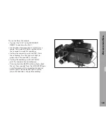
To use the D-21 with the fiber link unit:
Equip the D-21 with a
•
low mode short set.
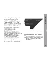
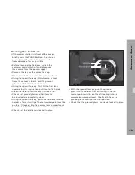
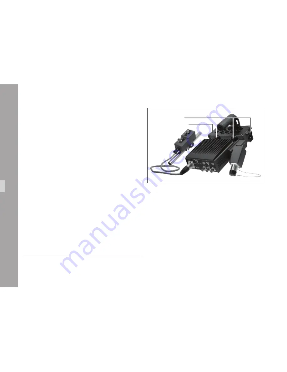
Attach the FLU-1 to the rear end of the short support
•
plate using the three fastening screws
➪
image
.
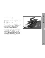
Connect the 24 V power cable included in
•
the Flash Mag/Sony Fiber Adapter Cable Set
(K2.70410.0) to the 24 V RS socket of the camera
and the RS power input socket on the FLU-1.
Connect
•
HD-SDI output A and B from one HD-SDI
output board to HD-SDI input A and B on the FLU-1.
Even in an HD422 setup, both connections are required.
The HD-SDI monitor output on the FLU-1
•
delivers a 4:2:2 return signal from the Sony
HDCAM SR field recorder that can be displayed
e.g. on the camera's onboard monitor.
Connect the SMPTE fiber cable to FLU-1 and recorder.
•
Set the desired output format parameters as described
•
in chapter 9: Camera Output Configuration.
On the recorder, setup the corresponding input
•
format and select the fiber interface input
[1]
.
Note: Using the FLU-1 requires no additional
setup on the camera side. Check the
instruction manual of the recorder in use for
information on setting up the corresponding
recording format using the fiber input.
[1] On the Sony SRW-1/SRPC-1, the optical input is selected by
setting Video I/O in the video setup menu to CAM(optical).
General requirements:
Sony SRW-1/SRPC-1 HDCAM SR field
•
recorder with an HKSR-101 fiber optic
adapter or another compatible recorder.
Variable frame rate recording on the Sony field recorder
•
additionally requires an HKSR-102 cache board.
Low mode short set (K2.70010.0).
•
Flash Mag/Sony Fiber Interface Cable Set
•
(K2.70410.0) for power and signal from camera.
Fiber optic cable 30 m/100 ft (K2.70500.0)
•
or 100 m/330 ft (K2.70501.0) for signal
connection to the recorder.
Fastening screws
Low mode short set


