C
a
m
e
ra C
o
n
fi
g
u
ra
ti
o
n
40
9. Camera Output Configuration
9.1.
Output Interfaces
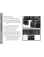
The ARRIFLEX D-21 has three output boards providing
HD and SD outputs on the back of the camera.
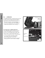
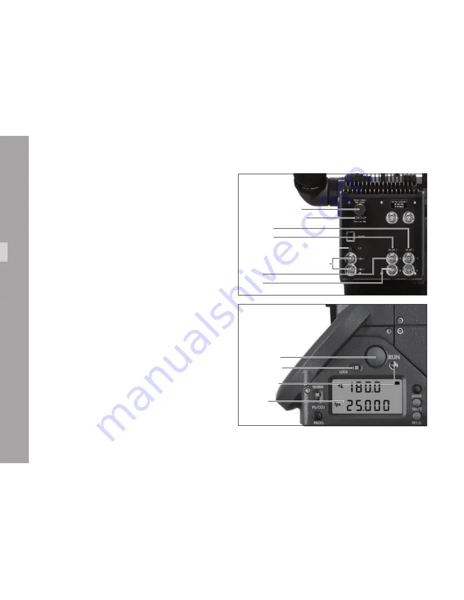
Two dual link HD-SDI outputs (
•
HD-SDI 1 and 2)
are located on the bottom right side
➪
image
.
Both BNC connectors on the top right output
•
a HD sync pulse. See chapter 11: Camera
Operation for more information.
Two composite video outputs (
•
CVBS 1 and 2)
and an S-Video output (Y/C) are located
on the bottom left side
➪
image
.
9.2. Video Menu
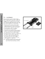
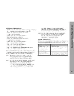
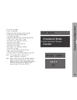
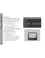
Most operational parameters for the ARRIFLEX D-21
are set using a video menu. The video menu is shown
as an on screen display on all SD video outputs.
Note: Configuration of the camera outputs requires
an SD monitor to be connected to one of the
composite video outputs or the S-Video output.
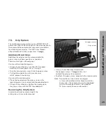
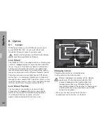
Note: Additional functions, including mirror shutter
angle and programmable frame rates, are
controlled using the camera display, located at
the front left side of the camera
➪
image
. See
chapter 11: Camera Operation for instructions.
Video menu button
Imaging status LEDs
S-Video, Y/C (SD output)
HD-SDI 2
Composite video (SD output)
HD-SDI 1
A link
B link
RUN button
LOCK switch
Operation
control LED
Camera
display

