S
ig
n
a
l C
o
n
n
e
c
ti
o
n
s
66
10.2. Signal Wiring Instructions
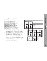
The following examples show signal wiring instructions
for different camera setups as explained in the previous
chapter. All setups requiring a single HD-SDI output
board can be combined using Advanced Mode setup, i.e.
HD422 up to 30 fps, HD444, Mscope and ARRIRAW.
Note: The shutter angles and frame rates shown in the
illustrations are only used as examples for settings
that match the corresponding digital setups.
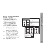
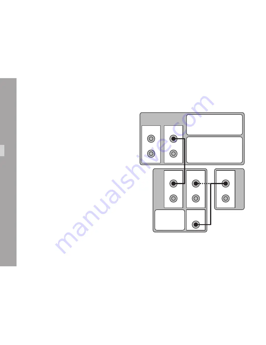
HD422 Setup (Standard Mode)
Set "Frame Rate" up to 30PsF.
•
Set "HD-SDI
•
Mode" to HD422.
• Set the recording system input format to 4:2:2 YCbCr
1080PsF/i using the frame rate set on the camera.
Connect camera output HD-SDI 1 or 2, link
•
A to recording input HD-SDI IN A.
Connect recording output HD-SDI OUT A or HD-SDI
•
monitor out to control monitor input HD-SDI IN A or B.
Note: When set to "HD422", the camera output
boards transmit the same signal on link A
and B. Using link A is recommended.
Note: Standard Mode setup assigns the same
settings to all HD-SDI output boards.
Individual configuration of the output
boards requires Advanced Mode setup.
B
A
C
on
tro
l M
on
ito
r
HD-SDI
IN
MONITOR
HD-SDI OUT
B
A
R
ec
or
di
ng S
ys
te
m
B
A
HD-SDI 2
B
A
HD-SDI 1
ARRIFLEX D-21
B
A
HD-SDI
OUT
Input Format:
4:2:2
24p/48i
HD-SDI
IN
On Screen Menu:
24 PsF
HD422
Normal Range
Camera Display:
∢
172.8
fps 24.000

