7
Product LayoutProduct Layout
7
Product Layout
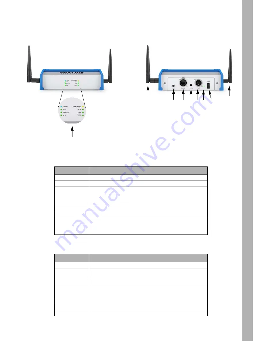
Overview of SkyLink Base Station
LED Indicators on the Front
Connectors and Switches on the Back
LED
Indication when lit
Power
The SkyLink Base Station is receiving power and switched on.
WiFi
A networked device is currently connected to WiFi.
Ethernet
Presence of an Ethernet port connection.
XLR
The SkyLink Base Station is accepting DMX input from local XLR port
instead of remote Art-Net/sACN from either Ethernet or WiFi.
CRMX Status
Operation of CRMX transmitter. Usually solid, blinks when linking.
RDM
Indicates RDM traffic.
DMX
Indicates DMX traffic.
DHCP
The SkyLink Base Station’s DHCP service is assigning IP addresses
to Ethernet and WiFi devices.
Feature
Description
Link Button
Links or unlinks receivers. Short press to link, hold 3 s to unlink all.
Ethernet
Standard RJ-45 Ethernet connector, EtherCON compatible. For use
with Art-Net and sACN communication.
12 V DC Input
Power Input - 2.1mm x 5.5mm Barrel (Center Positive).
DMX
5 Pin XLR Female. Default DMX OUT, can be configured from web
interface.
Reset Pinhole
Reset SkyLink Base Station to factory default settings.
Power switch
Switches the unit on or off.
Antenna
For transmitting DMX/RDM WiFi Data.
1
- Link button
2
- Ethernet connector
3
- Power input (12 VDC
4
- DMX connector
5
- Reset pinhole
6
- Power switch
7
- Antenna
1
2
4
6
7
7
LED indicators
5
3
Summary of Contents for SkyLink
Page 1: ...SkyLink Base Station and Receiver L5 0019058 U S E R G U I D E ...
Page 3: ...3 Dimensions Dimensions 3 Dimensions Base Station Receiver ...
Page 19: ......
Page 20: ......


