background image


!

34

!


15  

Status

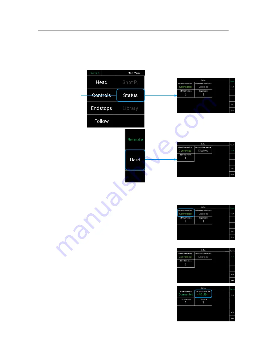
Selecting Status will open a new touchscreen display menu. The 

Status

 menu will display 

the status of controller expanders, wireless status, and status of individual connections. 

(LBUS, FS-CAN Bus, wireless connection)


Selecting 

Status

 will first 

open the 

Remote

 status. 


Selecting 

Head

 will open  


the 

Head

 status 

15.1


Head & Remote Status Displays 

The Remote and the Head Status screens indicates  

the status of the wired connection, the wireless connections 

LBUS and Expander controllers.

Wired Connection

 indicates that the FS Can Bus cable  

is connected. 

NOTE

Connecting the FS Can Bus cable, will overrule 

the wireless connection.  

The wireless connection will remain, but no data 

will be send as long the cable is plugged in. 

Wired NC

 indicates that the connection is now 

wireless

NOTE

As soon the FS Can Bus cable gets 

disconnected


and the radio module is switched enabled, all data 

will be transferred 

wireless

.

NOTE

The quality of the wireless connection will be indicated 

by the dBm value.  

Status

Head

Status

Remote

Summary of Contents for SRH-3

Page 1: ... 1 Remote Control SRH 3 Date 01 09 2018 USER MANUAL ...

Page 2: ...or other system components ARRI assumes no responsibility for any errors that may appear in this document The information is subject to change without NOTICE For product specification changes after this manual was published refer to the latest published ARRI data sheets or release notes etc for the most up to date specifications Not all products and or types are available in every country Please c...

Page 3: ...7 PID 16 7 PID Quick Setup 18 7 PID Drop 19 7 PID Autotune 20 8 Controls 21 9 Offset 25 10 Speed Ratio 27 11 Endstops 28 12 Follow Mode Pan Lock 30 13 True Horizon 32 14 Shot Preset 33 15 Status 34 16 Library 36 17 Settings 37 18 Wireless 39 19 Service 42 20 Info 44 21 FIZ 46 22 User Profiles 50 23 Accessories 52 24 Assignable controllers and functions 53 25 Pinout 54 Table of Contents ...

Page 4: ... hazardous situation which if not avoided will result in death or serious injury WARNING indicates a potentially hazardous situation which if not avoided may result in death or serious injury CAUTION indicates a potentially hazardous situation which if not avoided may result in minor or moderate injury NOTICE NOTICE explains practices not related to physical injury No safety alert symbol appears w...

Page 5: ... 12V Pwr Out FS Can Bus 12V Pwr In Main Pwr On Off LBUS In ARRI Mounting Rosettes Assignable Knob K7 Joystick Touch Panel Emergency Shut OFF Switch Cover optional module Assignable Button B1 Accessory mounting frame Cover optional module Assignable Button B2 Assignable Knob K8 Buttons B5 B6 Assignable Knobs K1 K2 K3 Assignable Knobs K4 K5 K6 Cover optional module Antenna Buttons B3 B4 Functions ...

Page 6: ...g the SRH 3 Stabilized Remote Head The SRH 3 can be hardwired with the Remote Panel using the FS CAN BUS connector NOTE Maximum cable length is 250 meter 820 feet 3 3 Powering Monitors and Accessories The SRH 3 Control Panel offers one ARRI RS and two Lemo 0B 2pin power out sockets NOTE The ARRI RS does not support the classic camera On Off trigger signal 12V Pwr In Main Pwr On Off FS CAN Bus FS C...

Page 7: ...H 3 Control Panel can be updated and serviced through the Mini USB socket 3 6 Antenna This is the connector for the SRH 3 antenna only RC Data FF Can Bus Mini USB Antenna Connectors NOTICE Check with the PLC website that your wheels have the correct firmware NOTICE Never use the Remote Control Panel without an antenna mounted Otherwise you will risk damaging the radio amplifier ...

Page 8: ... or other supported LBUS products NOTE When using two ARRI Master Grips or other supported LBUS controllers like the DRW 1 connect one controller directly to the second controller first Then connect the two daisy chained controller to one of the LBUS In sockets Connectors LBUS In ARRI Mounting Rosettes LBUS LBUS LBUS LBUS ...

Page 9: ...nly the motor power will be disconnected If the Emergency Shut Off switch had been used this message will appear in the control screen NOTE If the Remote Head does not react to the control panel even the main power switch is on check that the Emergency Shut Off Switch is pulled out NOTE To release the Emergency Shut Off Switch turn the red knob to the left Emergency Shut OFF Switch FIZ B6 B5 B3 Tr...

Page 10: ...ooth the axis movement starts and stops see page 22 Default Position Button This function will move the head back to its predefined starting position In this case this function is assigned to button B3 NOTE The pan and tilt axes will return to zero position and roll will remain where previously set If the roll axis is assigned to a Joystick or wheels then it will return to zero True Horizon B4 Set...

Page 11: ...hscreen menu opens to allow changes to increase decrease PID and motor power settings Main Menu Selecting Menu will return the display to the Main Menu and selection screen 5 Factory pre assigned controls Knob K7 Assignable Button B1 Assignable Button B3 Default Position Button B4 True Horizon Knob K1 Pan Speed Knob K2 Tilt Speed Knob K3 Roll Speed Knob K3 Roll Angle Button B2 Assignable Tilt Pan ...

Page 12: ...e and the function it has been assigned to control By example B3 will move the head back to its pre defined default position The button B3 is located here Joystick Indicates that the built in Joystick 1 is assigned for use with Tilt and Pan TS Indicates that the function is assigned to the touchscreen Assigning Controls Select one of the available controllers and confirm by touching Assign J1H Joy...

Page 13: ...ll open a new touchscreen display menu The Follow menu will control the speed Deadband and ramp of the optional follow mode for each axis In normal remote head operation the follow mode will be turned off Shot Preset Future feature Status Selecting Status will open a new touchscreen display menu The Status menu will display the status of controller expanders wireless status and status of individua...

Page 14: ... will provide additional information when activated FIZ Selecting FIZ will open a new touchscreen display menu The FIZ menu uses the LBUS connector to control supported LBUS devices Back Will bring you back to the previous menu window Home Will bring you back to the Home Screen page 10 Main Menu Selected Profile Head Adjustments Controls Adjustment System Adjustments Service Status Info FIZ Endsto...

Page 15: ...gs for each axis General Setup Standing normal Hanging underslung NOTICE Before using the SRH 3 the mounting position of the head needs to be set in the remote control Motors On Off PID Pan Axis Tilt Axis Roll Axis Selected Profile Back to the Home Screen Back to the previous screen Back to Factory Preset Store your adjustments Cancelation Motor Mode NOTICE You need to tell the RCP the current mou...

Page 16: ...tor power for each axis and save them as settings to the selected profile Head Menu Switching off individual motor axis means that the camera is no longer held in position and may suddenly move Make sure someone is taking care of the camera CAUTION Position Integral Pan Axis Tilt Axis Roll Axis Selected Profile Back to the Home Screen Back to the previous screen Back to Factory Preset Store your a...

Page 17: ...m I accounts for past values of the SP PV error and integrates them over time to produce the I term For example if there is a residual SP PV error after the application of proportional control the integral term seeks to eliminate the residual error by adding a control effect due to the historic cumulative value of the error When the error is eliminated the integral term will cease to grow This wil...

Page 18: ...driving the point 4 3 or if the camera is bouncing left and right 5 0 If the camera is over driving or bouncing you need to work on the P and D value of the Pan axis Adjust the P and D values by steps of five up or down 5 1 If the head is still bouncing because a too soft damper in between the Head and Crane increase the Ramp on the Joystick to slow down the mass before the targeted end position 5...

Page 19: ...a when the camera is facing down If the camera is tilted downwards on the tilt axis the overall length of the camera will be shortened as well as the weight distribution The compressed weight distribution can lead to overcompensation of the Pan axis The Drop function will help to prevent this The motor power of the Pan axis is regulated down in proportion to the tilt angle Depending of the length ...

Page 20: ... the same time Touching All PID Tune for example will open this screen NOTE During autotune calibration the head moves in all single axes which can cause vibration and possibly noise This is completely normal and there is no need to worry When the autotune has been completed the PID menu will show up again and will present the actual PID values Here you can accept the autotune PID values by pressi...

Page 21: ...s submenu allows the operator to assign specific controls to each axis for example a joystick knob wheels or a button Controls Menu Position Submenu Back to Factory Preset Store your adjustments Cancellation Offset Submenu Ratio Submenu Pan Axis Tilt Axis Roll Axis Back to the Home Screen Back to the previous screen Deadband Submenu Ramp Submenu Back to the Home Screen Back to the previous screen ...

Page 22: ...W 1 ARRI Wheels Tilt DRWR DRW Roll DRW 1 ARRI Wheels Roll V R VCW Roll PLC VC Wheels Roll V T VCW Tilt PLC VC Wheels Tilt V P VCW Pan PLC VC Wheels Pan EHDP EHD Pan EHD 1 ARRI Encoder Head Pan EHDT EHD Tilt EHD 1 ARRI Encoder Head Tilt TS Touchscreen Control through RCP K1 K8 Knob 1 Knob 8 Knobs B1 B6 Button 1 Button 6 Buttons V SR VCW Speed Roll PLC VCW Speed Roll Poti V ST VCW Speed Tilt PLC VCW...

Page 23: ...OTE The Deadband for this axis can only be changed if the assigned controler is a Joystick for example but not the touchscreen 8 6 Ramp Start Stop Submenu This selection will open a new touchscreen slider that allows you to change the Start Ramp and the Stop Ramp setting on the selected axis NOTE In the factory preset the Start and Stop Ramps are assigned to the knobs K4 K5 and K6 Turning the knob...

Page 24: ...lected tilt and pan speed Higher speed will produce a slower and more flat ramp Lower speed will produce a faster and steeper ramp NOTE This is useful for wide angle and standard lenses Constant Ramp The constant ramp Cons will keep the adjusted ramp regardless of the speed values NOTE This is very useful for tele lenses 8 8 Controls On Off NOTE By touching Controls On Off all input devices will b...

Page 25: ... needs to be assigned first NOTE In the default factory setup the Offset is assigned to the Touchscreen Knob 7 if it is available will be a very good choice for the Offset function Touching the field Control Touchscreen will open the assignment submenu Select K7 and touch Assign Turning Knob 7 off the center position will move the selected axis of the head with the adjusted speed of the knob NOTE ...

Page 26: ...the direction of the assigned controller 9 3 Deadband This selection will open a new touchscreen slider that allows you to change the amount of Deadband for the selected offset rate on each axis NOTE Deadband is defined as delay before the control device activates the selected function 9 4 Sensitivity This selection will open a new touchscreen slider that allows to change the sensitivity of the co...

Page 27: ...l be disabled when the speed function is assigned to a knob or to another controller The Slider displays the adjusted value of the knobs K1 K2 and K3 10 2 Ratio Controls Menu Selecting Ratio will open a new touchscreen display where you can select the required Speed Ratio of the selected axis Pan Tilt Roll NOTE When shooting with a extreme tele lens it can be very helpful to change the speed ratio...

Page 28: ...th a slider to allow the operator to set the left endstop position measured as an angle individually for each axis The Set Right Bottom Max selection will open a new touchscreen display with a slider to allow the operator to set the right Endstop position measured as an angle individually for each axis For example Move the head to the desired position at the left Angle will display the actual angl...

Page 29: ...t factory setup the Endstop On Off button is assigned to B5 The Endstop On Off button on the Home screen will turn on off all programmed Endstops Unassigning will move the function to the touchscreen Endstops Endstop Status ...

Page 30: ...s allows additional creative possibilities NOTE In the default factory setup the Follow mode is deactivated Selecting Follow will open a new touchscreen display menu The Follow menu will control the Speed Deadband and Ramp of the Follow mode individually for each axis 12 1 Follow On Off The Follow On Off selection will allow the operator to enable or disable the follow mode individually for each a...

Page 31: ...ow Deadband selection will open a new touchscreen display with a slider to allow the operator to set the Deadband of the follow function individually for each axis NOTE The Deadband should be 0 to max 30 to reach the so called Pan Lock 12 4 Follow Ramp The Follow Ramp selection will open a new touchscreen display with a slider to allow the operator to set the ramp rate of the follow function indiv...

Page 32: ...igned button B4 13 2 Precondition NOTE The used controller needs to be Wheels Joystick internal Zoom Rocker or Master Grip Zoom rocker NOTE The Roll Axis needs to be in Speed Mode 13 3 Usage By using one of the listed controllers the horizon can be adapted to the desired framing That means of course that the horizon in the frame may be offset to the physical Zero position To reach the physical Zer...

Page 33: ... Shot Presets menu will allow you to program up to 12 shot presets for up to 6 parameters including roll tilt pan focus iris and zoom These presets can be recalled using the touchscreen Shot Preset button on the home screen NOTE This function is currently disabled Shot Preset Shot Preset ...

Page 34: ...tus of the wired connection the wireless connections LBUS and Expander controllers Wired Connection indicates that the FS Can Bus cable is connected NOTE Connecting the FS Can Bus cable will overrule the wireless connection The wireless connection will remain but no data will be send as long the cable is plugged in Wired NC indicates that the connection is now wireless NOTE As soon the FS Can Bus ...

Page 35: ...heels and future controllers Head Will show the amount of connected LBUS Motors like the cforce Mini 15 3 Expander Status Display The Expander status row indicates the number of expander modules or control devices active on the remote control Following expanders are available Status Name Function JOY 1 Joystick 1 build in RCP 1 Knobs and Buttons of the remote control IWF 1 additional internal Focu...

Page 36: ...electing Library will open a new touchscreen display menu The Library menu will store controller setup files control assignments motor settings and shot presets NOTE This function is currently disabled Library Library ...

Page 37: ... the Remote Head and System will open up 17 1 Settings Remote 17 2 Display Rotation Selecting Rotation will open a new window The Settings menu allows invert the controller display 17 3 Brightness Display Selecting Brightness will open a new window The Settings menu will display the adjustable control panel brightness Settings ...

Page 38: ...treme centrifugal circumstances you can increase the overall stabilization by activating the High Dynamic Mode Settings NOTICE The activation of the High Dynamic Mode will take up to 5 10 seconds Do not move the head while the head is activating the High Dynamic Mode Each time the head and remote control are turned on again after a pause or battery change the High Dynamic Mode is reactivated This ...

Page 39: ...d radio connection on channel 13 Selecting System will open a new touchscreen display menu Here you can access the Wireless menu In this case the screen indicates that the wireless is On the system is on Channel 11 and that the region is Europe 18 1 Wireless On Off To enable or to disable the radio module touch Wireless and toggle between On and Off Off Wireless NOTICE To change any radio module re...

Page 40: ...ause 15 21 Changes or modifications not expressly approved by the party responsible for compliance could void the user s authority to operate the equipment Canada Contains IC 9482A EMIP400 This device complies with Industry Canada s licence exempt RSSs Operation is subject to the following two conditions 1 This device may not cause interference and 2 This device must accept any interference includ...

Page 41: ...cable The wireless connection will remain but no telemetry data will be send as long the cable is plugged in NOTE If you need a radio free hardwired connection you need to switch off the radio module and to connect head and remote via a FS Can Bus cable Wireless NOTICE Wireless region settings specify where the wireless function can be used in compliance with local regulations It may be illegal to...

Page 42: ...en a new touchscreen display menu here the remote control can be restored to the default factory settings NOTE Only the actual settings and values will be deleted by a restore NOTE After a restore you need to restart the remote head and the remote control by disconnect the power supply for a short while 19 3 Calibrate Joystick Selecting Calibrate Joystick opens a new touchscreen display menu in wh...

Page 43: ... supply for a short while 19 6 Restore Sensor Calibration Selecting Restore Sensor Calibration will open a new touchscreen display menu here you can restore the head to the factory settings 19 7 Calibrate Camera Gyro Selecting Camera Gyro will open a new touchscreen display menu and the gyro will recalibrated automatically Service NOTICE The remote head needs to be placed on an even ground and sho...

Page 44: ... serial number and firmware version of the remote control 20 2 Info Remote Control LBUS Touching LBUS will show you the serial number and firmware version of the supported LBUS controllers 20 3 Info Remote Control Expanders Touching Expanders will show you the serial number and firmware version of the FS Can Bus compatible controllers Info ...

Page 45: ...ead Mainboard Touching Mainboard will show you the serial number and firmware version of the remote head 20 5 Info Head LBUS Touching LBUS will show you the serial number and firmware version of the cforce motors Info ...

Page 46: ...ras and lenses NOTE Only supported LBUS products can be connected to the SRH 3 Remote Head 21 1 FIZ Configurations Master Grips Internal Focus Zoom controllers WCU 4 wireless Broadcast Internal Focus Zoom controllers Broadcast Master Grips FIZ Focus Zoom Iris Wired Wireless Focus Zoom Iris Wired Wireless Wired Wireless Focus Zoom Iris from RCP Wired Wireless Focus Zoom Focus Zoom Iris Or Iris from...

Page 47: ...1 Focus Wheel 1 Internal Focus Wheel 1 IFW2 Focus Wheel 2 Internal Focus Wheel 2 IZR1 Zoom Rocker 1 Internal Zoom Rocker 1 IZR2 Zoom Rocker 2 Internal Zoom Rocker 2 MLW Left Wheel Master Grip Left Focus Wheel MRW Right Wheel Master Grip Right Focus Wheel MLR Left Rocker Master Grip Left Zoom Rocker MRR Right Rocker Master Grip Right Zoom Rocker MLRB MLR Button Master Grip Left Rocker Red Button MR...

Page 48: ...menu 21 6 Motors On Off The Motors On Off selection will open a new touchscreen display These toggle switches allow you to turn On Off the motors for each axis individually Back to the Home Screen Back to the previous screen Focus Motor Iris Motor Zoom Motor Motors On Off Torque Mode Motor Calibration FIZ ...

Page 49: ...ng Calibrate every singe motor will be calibrated NOTE Green indicate that the motor had been calibrated Red indicate that the motor needs to be calibrated Quick setup procedure for cforce motors Mount the motors to the camera Connect each motor through LBUS cables Press the FIZ button at the motors to assign each motor to Focus Iris or Zoom Touch FIZ in the Home Screen Touch the field below the d...

Page 50: ...s assignments and settings are permanently written to the selected profile In this case in Profile 1 Each time changes are confirmed by Save or OK the changes are saved in the selected profile 22 1 Selecting User Profiles The Profile selection will open a new touchscreen display with a selection of profiles NOTE Selecting another profile the first time in this case Profile 3 will start with the de...

Page 51: ...o to Service through the Main Menu and select Remote Touching Factory Default will open a new window Touching Factory Default will open a new window NOTICE Selecting OK will restore all user profiles to the default factory presets All values and settings will be reseted User Profiles ...

Page 52: ...hapter mounting hardware a lot of adapters extensions and other useful bracketry is listed Shoulder Belt Adapters 2 0001223 34 17 gr Offers compatibility with standard ENG shoulder belts Rod Mounting Bracket RMB 2 Set 0 60209 0 180 K 0005807 The Rod Mounting Bracket RMB 2 can be attached to any ARRI 3 8 16 inch interface and holds a standard 19 mm rod 15 mm rod with a reduction insert includes K2 ...

Page 53: ...ker MRR Right Rocker Master Grip Right Zoom Rocker MLRB MLR Button Master Grip Left Rocker Red Button MRRB MRR Button Master Grip Right Rocker Red Button MLWB MLW Button Master Grip Left Wheel Red Button MRWB MRW Button Master Grip Right Wheel Red Button OCUW OCU Wheels OCU 1 Wheel OCUL OCU Left OCU 1 Left Button OCUM OCU Middle OCU 1 Middle Button OCUR OCU Right OCU 1 Right Button V F VCW Focus P...

Page 54: ...wr 12V Lötseite Buchse 1 GND 2 12V OUT LEMO ECG 0B 302 CLN 4 FS CAN Lötseite Buchse 1 GND 2 CAN1 L 3 CAN2 H 4 12V OUT 4 3 2 1 Fischer DGP 103 A053 140 6 REMOTE Connectors V1 4 1 2 AUX Pwr 12V Lötseite Buchse 1 GND 2 12V OUT LEMO ECG 0B 302 CLN 5 XLR Power IN 12V Lötseite Buchse Neutrik NC4MP B 2 4 3 1 1 GND 2 N C 3 N C 4 12V IN 7 LBUS Lötseite Buchse 1 GND 2 CAN L 3 12V 4 CAN H 1 2 3 4 LEMO ECG 0B...

Reviews: