background image

Table of Contents Continued 


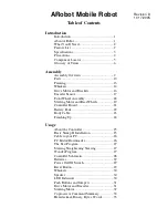
                                Connectors 


Battery Connector ..........................................36 


Body Connector .............................................36 


Serial Port Connector.....................................36 


RC Servo Motor Connectors..........................37 


DC Motor Connector .....................................37 


Powerful Output Connector ...........................37 


                                Expansion 


Expansion Connector.....................................38 


User RC Servo Motors...................................38 


Expansion Circuit Examples..........................39 


Coprocessor Network Expansion...................42 


Using Other Controllers.................................43 


                                Additional Information 


Suggested Reading.........................................44 


Component/Accessory Suppliers...................45 


Internet Robot Resources...............................47 


Troubleshooting .............................................49 


Warranty Information ....................................50 


ARobot Project Database –  

www.robotics.com/arobot/projects.html


ARobot FAQ –  

www.robotics.com/arobot/faq.html


Summary of Contents for ARobot

Page 1: ...Robotics com Assembly and User Guide Copyright c 2005 Arrick Robotics All Rights Reserved Mobile Robot For Hobbyist Research and Education ...

Page 2: ...y 18 Steering Motor and Rear Wheels 19 Controller Board 21 Battery Pack 22 Body Cable 23 Finishing Up 24 Usage About the Controller 25 Basic Stamp II Installation 25 Cable to your PC 26 PC Editor Downloader 26 The Test Program 27 Steering Straightening Steering 27 Wander Program 27 Controller Schematic 28 Batteries 29 Power On Off Switch 29 Reset Button 29 Whiskers 30 Speaker 30 LED Indicators 30 ...

Page 3: ...n Expansion Connector 38 User RC Servo Motors 38 Expansion Circuit Examples 39 Coprocessor Network Expansion 42 Using Other Controllers 43 Additional Information Suggested Reading 44 Component Accessory Suppliers 45 Internet Robot Resources 47 Troubleshooting 49 Warranty Information 50 ARobot Project Database www robotics com arobot projects html ARobot FAQ www robotics com arobot faq html ...

Page 4: ...use concepts such as computer programming motion control sensor reading path planning object avoidance and more Easily assembled in a few hours using common hand tools no soldering required Connect ARobot to your personal computer for programming and begin your adventure Basic Stamp II Control Computer The Basic Stamp II is a small self contained computer controller manufactured by Parallax Inc Th...

Page 5: ... defined RC servo motor control ports Serial communications port Program using a desktop PC then download for autonomous operation Expansion port allows unlimited possibilities Mounting holes for Radio Shack Breadboard or perfboard Coprocessor network allows multiple processors to communicate and distribute tasks Application notes for sonar range finding head light light sensors compass and more W...

Page 6: ...ling and bearings Optical wheel encoder for distance measurement Encoder 20 counts per revolution 2 per inch of travel 1 2 resolution Motor driver H bridge 1 amp max Speed control Pulse Width Modulation Controller PCB size 2 1 x 6 Steering Motor Standard size RC servo motor Power source 8 AA cells in removable pack Runs on 8 AA cell batteries for 5 hours or more Current draw 50ma at standstill 200...

Page 7: ...ot in areas near water such as swimming pools Never allow the whisker wires to be inserted into electrical outlets or other dangerous places Never use the robot in areas that could result in a fall such as lofts stairways hills Never allow cables to fall out or to be broken by the robot s motion Never control devices with the robot that could be dangerous to life or property such as lawn mowers or...

Page 8: ...teering Linkage Controller Whiskers 5V Voltage Regulator RC Servo Motors Body Connector Serial Port Speaker Drive motor Connector Green LED Battery Connector Powerful Output H bridge Expansion Connector Reset Jumpers Buttons Coprocessor Basic Stamp Proto Area Power Switch Front Right Side Battery Pack Steering Arm Drive Motor Encoder Wheel ...

Page 9: ...sed Loop In motor control the use of a feedback device such as an encoder to adjust the motor driver to achieve the desired position speed or acceleration ARobot s drive motors are closed loop Compiler A program that converts a high level program into a low level program that can be executed directly by a CPU Digital Signals Signals that can have a value of on or off 1 or 0 Encoder A feedback devi...

Page 10: ...invisible to the human eye IR is used by most TV and Stereo remote controls Also see Passive Infrared Integrated Circuit IC A device where many electrical components are built together as a single component ARobot uses integrated circuits on it s circuit boards to perform most functions Interpreter A computer language that converts instructions while the program is running Unlike a compiler that f...

Page 11: ...tance Resolution In a motor control system the smallest motion that a motor can make Robot Any device that operates automatically performing tasks like a human Rule based System See Expert Systems Sensor A device that converts light temperature and other phenomena to electrical signals Also re ferred to as transducer The ARobot uses many different sensors to detect the environment Serial Data Data...

Page 12: ... do these things Sand and paint the metal robot body pieces this is optional Mounting whiskers drive motor steering motor wheels etc Route cables Install the Basic Stamp II onto the controller board You ll learn Identification and names of all parts Screw nut and washer sizes Basic electronic terminology Basic mechanical assembly techniques Basic wiring skills Tools you ll need Medium Phillips scr...

Page 13: ... 4 Plastic wire tie Bundling wires 1 Body Cable Connects controller to whiskers and encoder sensor 1 Encoder sensor To sense encoder wheel slots mounts to motor bracket 1 Shaft coupling Attach front wheel axle to drive motor 8 Collar Rear wheel assemblies 2 Rear axle Rear wheels 1 Front axle Front wheel assembly Don t damage threads 1 Bronze bearing Front axle 2 Steering arm Connects steering link...

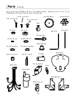
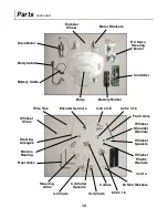
Page 14: ...0 star Steering Arm Washer 6 plastic Washer 6 shoulder Drive Motor Front Axle Rear Axle Steering Motor Collar Coupling Spacer 1 plastic Horn Motor Brackets Robot Body Here are drawings of SOME of the parts in the ARobot package Drawings are not to scale As you build ARobot refer back to these drawings to identify parts Bronze Bearing MTA Connector Body Cable ...

Page 15: ...eering Motor Body Encoder Wheel Whisker Wires 4 40 nuts Steering Linkages Steering Arms Rear Axles 10 32 nuts Encoder Sensors Controller Spacers Whisker Spacers Whisker Shoulder Washers Front Axle 4 40 x 3 8 4 40 x 3 16 Whisker Plastic Washers Velcro Wire Ties Collars Bronze Bearing 6 32 x 1 4 4 Star Washers ...

Page 16: ...irections on the paint can You may want to check out some of the non conventional paints that add texture to a surface Normally you should let the finish coat dry overnight before continuing Accents Be creative consider using special accents to make your robot stand out Masking to create special shapes such as flames or zebra stripes Colored electrical tape from Radio Shack Catalog 64 2340 Colored...

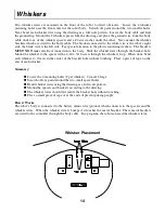
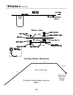
Page 17: ...e whisker wires through the bracket hole Mount the whisker to the spacer with a 4 40 x 3 16 screw through the whisker s loop When done bend each whisker so it rests in the center of the bracket hole without touching Place a piece of tape on the end of each whisker Summary Locate the 4 mounting holes 2 per whisker 2 small 2 large Scratch off any paint around the two small spacer holes Bend whisker ...

Page 18: ...Whiskers continued 15 3 4 1 1 2 Small Loop Attaches to Whisker Spacer Full Scale Whisker Wire Pattern 8 3 4 Total Length Bend both whisker wires using this pattern Whisker Detail ...

Page 19: ...obot s body using 3 screws 3 star washers and 3 nuts per motor bracket Minor bend ing may be required to align the mounting holes Summary Locate the 2 motor brackets left and right sides and the drive motor Mount the drive motor to the left bracket using 3 screws Locate the 6 motor bracket mounting holes on the robot body 3 per bracket Mount both brackets to the robot body Motor Bracket Placement ...

Page 20: ...eth that interrupt the beam of light Locate the encoder sensor and notice the dots placed on it see the drawing Mount the sensor using 2 screws 2 star wash ers and 2 nuts The encoder wheel will be mounted to the axle later Summary Locate the encoder sensor Mount the encoder sensor on the right wheel bracket according to the drawing 17 Encoder Wheel Encoder Sensor ...

Page 21: ...ng tighten On the long axle side slide on a star washer then screw on a nut tighten On the long axle side screw on a nut a washer then another nut per the drawing Slip the bronze bearing onto the long side of the axle flange first Insert the long axle side through the hole in the right motor bracket and the coupling on to the drive motor shaft The bronze bearing should fit in the hole If not use a...

Page 22: ...hows Mount the steering motor to the robot body per the drawing Mount the rear axles to the robot body using collars You may have to put 6 32 x 1 4 screws in each collar first Mount the wheels to the axles using collars Attach the linkages to the steering motor and to both steering arms Attach the steering arms to the axles Straighten the system put the steering horn in the center of travel loosen...

Page 23: ...Steering Motor Mounting Steering System 20 Steering Motor and Rear Wheels continued Wheel and Axle ...

Page 24: ...es that match the 4 mounting holes on the corners of the controller board There are 2 sets of mounting holes select the set towards the robot s rear Install the 4 spacers in those holes The controller board will simply snap onto these spacers and can be removed any time The 9 pin serial port connector should point towards the rear of the robot the expansion connector will be towards the front Summ...

Page 25: ... robot body make sure the cable can reach Connect the cable and mount the battery holder Summary Don t install batteries yet Locate the battery cable Plug the cable into the controller board Route the cable through a nearby hole in the body Place one side of the Velcro strip on to the battery holder Place the other side of the Velcro strip on the bottom of the robot where the cable can reach it Co...

Page 26: ...the body cable into the controller s 10 pin body connector which is next to the expansion connector It will only install one way Next find the 2 MTA connectors on the body cable Attach them to the encoder sensor by match ing the dots Summary Route the body cable up through the opening in the body Plug the cable into the body connector on the controller board Plug the MTA connectors onto the encode...

Page 27: ...ellow wire to pin 1 Installing this cable backwards will not harm the motor or controller but it will not work Use the plastic wire ties to attach the body cable to the robot body Use any unused holes in the body You can also attach the steering motor and the battery cable if you want Route the drive motor cable up through the rectangular opening in the body and attach it to the motor connector on...

Page 28: ...a Battery Connector Power Switch Reset Button Buttons Jumpers Speaker Coproces Basic Stamp Powerful Output Basic Stamp II Installation The Basic Stamp II is the computer that controls the robot It plugs into the controller board When in stalling the Basic Stamp II remove the battery cable from the controller then insert the pins into the socket noticing the pin 1 indicator Make sure that no pins a...

Page 29: ...nd also their documentation which gives greater detail about programming than we can offer here Install the software by coping the disk contents to a newly created directory on your hard disk Then run the editor downloader which is named STAMPW EXE for the windows version or STAMP2 EXE for the DOS version The program will require that you select the serial COMM port number Overview of programming ...

Page 30: ...ht and back again Jumpers One jumper causes the drive motor to move forward The red LED will go on and off as the motor turns indicating an operating encoder The other jumper turns on the powerful output If one button is pressed the powerful output will reverse polarity Steering Adjustment Program STRAIGHT BS2 This program helps the robot builder adjust the steering system for straightness The pro...

Page 31: ...About the Controller Board 28 ...

Page 32: ...e that the drive motor will be slow and erratic operation or re sets may occur This will not harm the robot The power switch is located next to the power connector on the controller board The ON position is shown by a green dot The OFF position is shown by a red dot Make sure to turn power off when at taching cables installing batteries or installing the Basic Stamp or other parts Power On Off Swi...

Page 33: ...oles are provided for side and rear whiskers Speaker A speaker is connected to P9 on the Basic Stamp II It can be used to send various signals to the opera tor Simply toggle the pin at various frequencies to create different tones Here s a PBasic code exam ple speaker con 9 Define speaker pin to 9 freqout speaker 200 1500 200 frequency 1500 duration low speaker Finish with pin LOW It s very import...

Page 34: ...ives commands from the Basic Stamp II using serial I O commands over the coprocessor network pin P8 This frees the Basic Stamp II for other tasks An encoder wheel and encoder sensor are used to measure rotation of the drive wheel resulting in dis tance measurement There are 20 encoder slots counts per revolution As it rotates the slots are de tected by the encoder sensor The drive wheel is about 3...

Page 35: ...n 1 255 0 off 128 center The servo is moved to the desired position for 500 ms then turned off to conserve power rcservo serout net baud 1R dec1 motor hex2 position Move Motor serin net baud charn Get A pause 500 Wait for servo to turn serout net baud 1R dec1 motor 00 Motor off serin net baud charn Get A return If you need your RC servo motor to resist movement after it has turned to the desired p...

Page 36: ...ster Slave network The Basic Stamp II is the master and the coprocessor is the slave This creates a multi processor system Each command intended for the motor control coprocessor begins with 1 Drive Motor Control Example 1M11200E7 The command begins with 1M1 to indicate the drive motor The next character 1 in the example indicates the direction 1 forward 0 reverse The next character 2 in the examp...

Page 37: ...s followed by a character indicating the action 0 off 1 forward 2 reverse If the command is accepted an A will be returned indicating acknowledged Coprocessor Communication Rules Communication between the Basic Stamp II Master and the coprocessors follow these rules Single wire bidirectional serial communication Serial communication parameters 2400 baud 8 data bits and 1 stop bit Coprocessor netwo...

Page 38: ... bits A byte can be represented as a hex value such as 00 or FF The range of values that a byte can represent is 0 255 decimal 00 FF hex Words A word consists of 2 bytes 16 bits A word can be represented as a hex value such as 0000 or FFFF The range of values that a word can represent is 0 65535 decimal 0000 FFFF hex The following table shows the binary equivalent for each hex digit Hex digit Bina...

Page 39: ...ata from Basic Stamp II 3 Receive data to Basic Stamp II 4 Attention signal 5 Ground 6 Jumpered to pin 7 7 Jumpered to pin 6 8 No connect 9 No connect Usage Connects controller to encoder whiskers and ground lug Connector 10 pin dual row header 1 Pinout 1 P0 on Basic Stamp II whisker 1 2 P1 on Basic Stamp II whisker 2 3 P2 on Basic Stamp II optional 4 P3 on Basic Stamp II optional 5 Encoder 1 outp...

Page 40: ... 2 5 volts 3 Ground Drive Motor Connector J10 Usage Connects H Bridge driver to DC motors Controlled by coprocessor Polarity can be con trolled Type 2 pin MTA 1 Voltage 12 volts Maximum Current 500ma Pinout 1 2 Usage Connects H Bridge driver to accessory devices such as a DC motor or light Controlled by coprocessor Polarity can be controlled Type 2 pin MTA 1 Voltage 12 volts Maximum Current 500ma ...

Page 41: ...RC servo motor 2 25 RC servo motor 3 26 RC servo motor 4 27 No connect 28 No connect 29 No connect 30 No connect 31 No connect 32 No connect 33 No connect 34 No connect 35 No connect 36 No connect 37 No connect 38 No connect 39 No connect 40 No connect Usage Connects controller to user devices Connector 40 pin 1 IDC Header All four RC servo motor signals are available on the expansion connector fo...

Page 42: ...rd and the other set can be used to mount breadboards or perfboards Soldering and other basic electronic skills Books are available from Radio Shack and other sources that teach basic electronic skills such as component identification and soldering These subjects are beyond the scope of this text and will not be taught here Expansion ideas in this book require these basic skills and knowledge Expa...

Page 43: ...This example shows how to attach logic gates to the digital input signals Digital Power Output The digital signals can be used to control external circuitry Large loads can be driven with an external power transistor such as a MOSFET A clamping diode should be included to protect the transistor when switching inductive loads such as relays Power Output Example Digital Output Example More expansion...

Page 44: ...mple code This routine demonstrates detecting light The light level is read by determining the time it takes to charge the capacitor The CDS photodetector changes resistance as the light intensity changes This changes the current that is charging the capacitor The output result is then output to the debug screen light var word light variable main pause 500 check every half a sec low 2 drain cap pa...

Page 45: ... coprocessor A Basic Stamp II is an excellent choice because it doesn t need any external circuitry to communicate with ARobot s controller The Basic Stamp II can also be programmed by plugging it into ARobot s controller which eliminates the need for a programmer Communications ARobot s controller can communicate in a serial fashion with the coprocessor using the dedicated co processor network pi...

Page 46: ...pinout in the schematic for pin numbers and signal usage Cabling to the Basic Stamp II socket will allow access to the RS 232 connector raw DC voltage and the reset button These signals could also be wired to unused pins on the expansion connector if needed Signals that go directly from the Ba sic Stamp II socket to the Expansion connector and are not used anywhere else can be ignored The ones you...

Page 47: ...gence Computer Applications Journal 4 Park St 20 Vernon CT 06066 203 875 2751 Monthly periodical covering computer control projects Embedded Systems Programming Miller Freeman Inc 600 Harrison St San Francisco CA 94107 415 905 2200 Monthly periodical covering embedded computer programming Robot Builder s Bonanza By Gordon McComb Tab Books ISBN 0 8306 2800 2 Book popular among some robot hobbyist c...

Page 48: ...d to help in the expansion of ARobot These vendors offer such items as single board computer sensors and actuators Most of the companies listed have catalogs which contain detailed part and technical information and can be obtained at little or no cost McMaster Carr Supply Company P O Box 740100 Atlanta GA 30374 404 346 7000 Huge catalog containing mechanical parts tools and materials Mouser Elect...

Page 49: ... hardware Metric sizes Several catalogs and technical books are available SuperCircuits 13552 Research Blvd B Austin TX 78750 512 335 9777 Small video products including cameras and transmitters Tower Hobbies P O Box 9078 Champaign IL 61826 9078 800 637 6050 Catalog lists a wide variety of model kit components such as servos and linkages 46 Winfred M Berg 499 Ocean Ave East Rockaway NY 11518 516 5...

Page 50: ...robotics com robomenu The RoboMenu allows you to show off your robot www robotics com motors html What s the difference between servo and stepper motors www robotics com highload html Driving high power loads www controlled com Journal of Computer Controlled Systems PC 104 www dprg org Dallas Personal Robotics Group www frc ri cmu edu robotics faq The Robotics FAQ Frequently Asked Questions www nc...

Page 51: ...comp std wireless Examining standards for wireless network technology comp sys transputer The Transputer computer and OCCAM language misc books technical Discussion of books about technical topics misc creativity Promoting the use of creativity in all human endeavors rec games mecha Giant robot games rec models rc Radio controlled models for hobbyists rec radio amateur digital misc Packet radio an...

Page 52: ... wheel assembly is tight Problem ARobot will not move even though the drive motor is turning Remedy Tighten all the nuts on the front drive axle Don t damage the threads of the axle If the rubber part of the wheel is turning against the plastic hub you ll probably have to squirt some glue between the rubber and the plastic to keep them together Problem ARobot quits working when the drive motor or ...

Page 53: ... implied warranties for this product including the warranties of merchantability and fitness for a particular purpose are limited in duration to a period of one 1 year from the date of purchase and no warranties whether expressed or implied will apply after this period If this product is not in good working order as warranted above your sole remedy shall be repair or replacement as provided above ...

Page 54: ...Robotics com ...
Reviews: