REVERSE SMART AEB OPERATING MANUAL
Page
12
of
12
July 2017
6.2
Maintenance and Testing
Procedure:
1. Clean the sensor housing of any accumulation of dirt, mud, snow, ice or any other debris.
2. Visually inspect the Sensor and Display to ensure they are securely attached to the vehicle
and are not damaged.
3. Visually inspect the sy
stem’s cables to ensure they are properly secured and not damaged.
4. The location of the test should ensure the area in front of the sensor is clear of obstacles and
is larger than the detection range of 4meters.
If any of the following tests fail, follow the fault finding guidance in Section 4.1
“Initial System
Power Up and Test” of the installation guide.
For the following tests, the driver requires objects to be placed in the detection area or an assistant
(to observe the display indications).
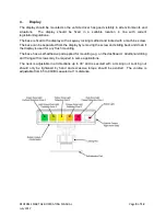
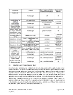
5. Activate the System (ensure the vehicle cannot move) to ensure the Status Light is illuminated
constant green on the display within less than 7 seconds.
6. If the display shows any of the 5 Zone Lights activated, this indicates there are likely to be one
or more objects in the detection area interfering with the test. Move the vehicle to a clear area
and proceed.
7.
Verify each detection zone’s distance: Starting from the outside of the detection area, the
driver should check several points along the centre line of the detection width down to around
0.4m distance from the sensor. The display should show the detection alerts via the lit Zone
Lights, the buzzer pulsing speed and, if the trigger output is used, the connected device or
function. The driver should note down the distance at which each detection zone is activated
and if it is in line with the installed system or the configuration for this vehicle.
8.
Close detection behaviour
: Verify objects in between 0.3m and 1.3m distance are only
detected if they move relative to sensor. All Zone Lights except for red should be constantly
active. The red colour Zone Light should stay active for systems covering more than 1.1m
distance with the closest detection zone 1.
9.
Very close detection awareness
: Verify objects less than 0.3m from the sensor are not
detected. All the Zone Lights and buzzer output should switch off after less than 3 seconds
with only the Status Light remaining illuminated constant green.
10. Similar to the previous tests the driver should scan all the edges of the detection area
according to the installed system or configuration for this vehicle. The driver should note down
the detected locations and check if they match with the detection area set when the Reverse
Smart System was installed on this vehicle.
More frequent inspections should be performed in cases where:
The vehicle is operating in a particularly dirty or harsh environment.
The operator has reason to suspect the system is not working or has been damaged.


