background image

OPERATING AND MAINTENANCE MANUAL FU 321M

28

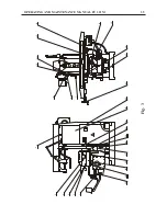
COMPONENTS LAYOUT

А

16

H

Q1

A6

S

5

A6

S

4

AS

5
5

AS

56

AS

53

AS

51

AS

54

AS

52

M1

M4

M5

AS

62

AS

61

AS

63

AS

21

AS

22

AS

33

AS

32

AS

31

AS

45

AS

44

AS

3
1

A1

S

8

A2

7

AS

42

AS

41

AS

43

A1S

5

A1

S6

R1

A1

S

2

AS

14

AS

11

AH

1
1

AS

7
1

A0

M

2

3

A0

M

1

3

Summary of Contents for FU 321M

Page 1: ...Operating and maintenance manual UNIVERSAL MILLING MACHINE FU 321M Arsenal Company 100 Rozova dolina Str 6100 Bulgaria tel 359 431 633 22 634 31 telex 088 507 F ARS BG fax 359 431 633 32 631 87 E mai...

Page 2: ...HEAD VFG 281 VFG 323 Operating and Maintenance Manual UNIVERSAL DIVIDING UNIT UDA 125 UDA 160 Operating and Maintenance Manual INDEXING TABLE KDM 320 Operating and Maintenance Manual SLOTING HEAD SG...

Page 3: ...TION 2 SAFETY PRECAUTIONS 3 SPECIFICATIONS 6 TRANSPORTATION AND INSTALLATION 8 PACKING LIST 11 TEST CERTIFICATE 13 OPERATION 15 DESCRIPTION OF THE MAIN MACHINE UNITS 19 LUBRICATION 21 COOLING SYSTEM 2...

Page 4: ...UAL FU 321M 1 TYPE UNIVERSAL MILLING MACHINE MODEL FU 321M Modification normal tropical metric inch Main motor range standard option Main motor power standard option YEAR OF PRODUCTION SERIAL No INVEN...

Page 5: ...types of cutters Various planes grooves gear wheels can be machined it is capable of boring in steel cast iron nonferrous and plastic parts The machine can carry out automatic pendulous and semi auto...

Page 6: ...perate the milling machine while your senses are impaired by medication drugs alcohol or other substances Always use safety gear safety glasses shoes etc Never use gloves which could become caught in...

Page 7: ...t the machine when the tool is touching the workpiece After mounting the tool carry out a trial run Do not operate the machine in automatic mode in the beginning Do not use compressed air to clean or...

Page 8: ...ve we hereafter state the noise output values for the machine 1 acoustic pressure level value at dB idle running of main drive at max speed 2 acoustic pressure level value when cutting less than 82 dB...

Page 9: ...r to yoke mm 150 Distance from floor to spindle center mm 1430 Table Working table size mm 320 x 1350 Table swing to left and right degrees x 45 Table travel longitudinal manual mm 1000 automatic mm 9...

Page 10: ...Spindle nose ISO 50 Spindle bore mm 29 Spindle dia at front bearing mm 110 No of spindle speeds No 18 Spindle speed range standard min 1 32 1600 option min 1 40 2000 Drive Main motor power standart k...

Page 11: ...installation it should be cleaned from the rust preventing oil with pure diesel oil For removal of protective oil film do not use solid objects and diluents that can damage the metal surfaces paint an...

Page 12: ...um 350 mm After final curing of the concrete tight the nuts of foundation bolts if used as continuously observe and keep not to disturb the horizontal leveling of the ma chine Then fill the space betw...

Page 13: ...consists of 2 front doors and 2 side panels Before proceeding with any kind of operation the both front doors should be closed The fitting of the table guards is done by M8 bolts on both sides of the...

Page 14: ...V Hz 1 6 Cooling system in a set with 3041 70 00 00 1 pump type Hz V min 1 1 7 Lubrication system with drive motor 1 type No kW V min 1 Hz 1 8 Lubrication unit with dosed feeding 1 No kW V min 1 Hz 1...

Page 15: ...ate Ser No partlist 3 7 Rotary index table KDM 320 1 Separate Ser No partlist 3 8 Slotting head SG 321 1 Separate Ser No partlist 3 9 Vertical milling head VFG 323 1 Separate Ser No partlist 3 10 Univ...

Page 16: ...018 mm No 1 2 3 4 5 6 7 8 2 1 Straightness on Table Top concavity is allowed 2 2 Parallelism of the Table Longitudinal Movement to Table Reference T Slot Side 2 3 Squareness between Cross and Longitu...

Page 17: ...le in vertical and horizontal plane 2 14 For machines with fixing element 2 15 For vertical milling machines 3 4 Straightnes of plane 1 and plane 2 side and top 3 5 Parallelism of sample workpiece pla...

Page 18: ...ening handle 15 Handle for cross feed on off 16 Handle for longitudinal screw backlash elimination 17 Handle for vertical feed on off 21 Handwheel for longitudinal table travel 22 Back cover 23 Cover...

Page 19: ...gency Stop buttons 45 or 51 Fig 3a and make a note of how long it tooks for spindle to stop The function of each button should be checked sepa rately Then start the machine in exactly the same way and...

Page 20: ...y the handle 4 Fig 3 SELECTION OF CROSS AND VERTICAL FEEDS Manual feed in cross and vertical direction is accomplished by handle 1 Fig 3 Remove the handle from the machine before putting on the automa...

Page 21: ...h Pos 47 Fig 3a should be in OFF position the operating mode selector 43 Fig 3a should be in position Immobile spindle The feed motions and the rapid traverse movement on the axes in the desired direc...

Page 22: ...They are tightened to the Yoke by means of nuts 11 Fig 3 The radial backlash of bearing 7 Fig 1 A A is adjusted by nut 8 The good functioning of the bearings 7 depends on the proper backlash adjustmen...

Page 23: ...ve the cover 30 Fig 3 and then take the split pin 2 Fig 6 out The manual cross feed is switched off by cams 28 Fig 3 and microswitches 29 Fig 3 and the vertical by cams 24 Fig 3 and microswitches 27 F...

Page 24: ...urer before the delivery of the machine For special operations the time for lubrication is necessary to be changed see Operating and Maintenance Manual of System for lubrification Pour the oil after r...

Page 25: ...rust it can cause to exposed metal surfaces as well The motor pump situated at the back part of the column is started by a switch Coolant ON OFF Pos 44 Fig 3a on the control panel The coolant driven b...

Page 26: ...ty stickers provided by the manu facturer It is important to provide safety gear appropriate tools adequate lighting material and spare parts with the same or equivalent specifica tions as the origina...

Page 27: ...n the spindle nose and check for cracks or other visible damage and that the work holding can be performed smoothly MONTHLY MAINTENANCE Continue with the weekly maintenance Clean the electrical contro...

Page 28: ...9 45 x 78 x 20 1 6 206 6206 30 x 62 x 16 3 7 7305 30305 25 x 62 x 18 5 1 8 7205 30205 25 x 52 x 15 2 9 7000103 16003 17 x 35 x 8 2 10 11 12 13 14 15 16 17 18 19 20 21 22 23 24 105 6005 2 x x 5 47 2 2...

Page 29: ...power cable 4x6 mm2 when four wire mains is used and 5x6 mm2 in case of five wire mains The cable passes through the electric inlet placed on the electric box It is connected to main breaker s Q1 ter...

Page 30: ...er Solid rectifier Lamp Resistor condenser diode Relay Contactor Contactor Contactor Emergency stop Pushbutton Pushbutton Pushbutton Selector switch 3 position Selector switch 2 position Switch Micros...

Page 31: ...T 16 H Q1 A6S5 A6S4 A S5 5 A S 5 6 A S 5 3 A S 5 1 A S 5 4 A S 5 2 M1 M4 M5 A S 6 2 A S 6 1 A S 6 3 A S 2 1 A S 2 2 A S 3 3 A S 3 2 A S 3 1 A S 4 5 A S 4 4 A S3 1 A1S8 A27 A S 4 2 A S 4 1 A S 4 3 A1S5...

Page 32: ...OPERATING AND MAINTENANCE MANUAL FU 321M 29 ELECTRIC EQUIPMENT DETAILS...

Page 33: ...OPERATING AND MAINTENANCE MANUAL FU 321M 30 ELECTRIC ARRANGEMENT...

Page 34: ...OPERATING AND MAINTENANCE MANUAL FU 321M 31 BUTTON ARRANGEMENT FRONT PANEL 10...

Page 35: ...OPERATING AND MAINTENANCE MANUAL FU 321M 32 BUTTON ARRANGEMENT SIDE PANEL WARNING...

Page 36: ...OPERATING AND MAINTENANCE MANUAL FU 321M 33 Fig 1 DRAWINGS AND CHARTS A A 7 8 10 1 2 3 4 5 A A 6 9...

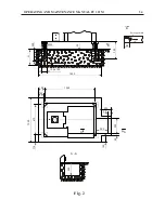
Page 37: ...OPERATING AND MAINTENANCE MANUAL FU 321M 34 Fig 2 M22 300 20 H 250 100 x 100 1500 1250 125 100 670 1020 175 140 300 300 250 50 50 A 250 100 95 Earting point M8 B B...

Page 38: ...OPERATING AND MAINTENANCE MANUAL FU 321M 35 Fig 3 1 2 3 4 5 24 25 24 26 27 28 29 28 30 22 23 6 8 7 9 10 11 12 13 14 15 16 17 21...

Page 39: ...OPERATING AND MAINTENANCE MANUAL FU 321M 36 Fig 3a 45 41 46 51 48 43 52 44 42 53 49 50 47...

Page 40: ...OPERATING AND MAINTENANCE MANUAL FU 321M 37 SEMI AUTOMATIC CYCLE...

Page 41: ...OPERATING AND MAINTENANCE MANUAL FU 321M 38 Fig 4 12 5 69 8 5 128 57 0 018 2 12 27 39 6 0 25 7 24 4 6 1 25 140 36 6 101 0 5 17 25 4 0 04 0 0 17 0 45 45 1 2...

Page 42: ...OPERATING AND MAINTENANCE MANUAL FU 321M 39 Fig 5 320 4 x 18 0 43 12 1 2 3 18 0 027 30 30 63 63 90...

Page 43: ...OPERATING AND MAINTENANCE MANUAL FU 321M 40 Fig 6 1 2...

Page 44: ...OPERATING AND MAINTENANCE MANUAL FU 321M 41 Fig 9 Fig 8 WARNING Disconnect the mains supply before removing this cover 1 4 2 3 18 17 16 15 14 13 1 2 3 9 8 7 5 4 6 11 10...

Page 45: ...box and in the knee is performed after 300 operating hours the second after 500 the third after 1500 and then after each 4000 operating hours It is recommended to wash the spindle gear box and the kn...

Page 46: ...OPERATING AND MAINTENANCE MANUAL FU 321M 43 Fig 10 4 3 2 1...

Page 47: ...Fig 13 13 32 x 3 5 12 45 x 3 5 11 47 x 4 14 66 4 x 10 43 x 4 5 21 x 4 6 25 x 4 7 48 x 3 8 62 x 3 5 9 16 x 4 IV III 4 33 3 5 x 3 16 x 3 2 22 x 5 3 II I D 272 mm 1 1 2 x 8 4 D mm 160 2 204 mm 140 mm 17...

Page 48: ...II 2 73 x 2 30 22 x 2 5 III 29 35 x 2 5 IV V 28 28 x 2 5 VI VII 27 40 5 x 2 26 40 5 x 2 25 18 x 2 5 24 173 x 23 23 x 2 22 23 x 2 21 27 x 2 20 54 x 2 XII 11 17 x 2 5 12 36 x 32 5 13 15 x 32 5 XI X IX V...

Page 49: ...OPERATING AND MAINTENANCE MANUAL FU 321M 46 Fig 15 I II III IV V VI VII XII XI X IX VIII 10 11 12 13 13 14 15 16 17 18 19 6 20 21 3 9 8 7 4 5 22 21 22 23 22 6 6 24 3 2 1...

Page 50: ...E MANUAL FU 321M 47 ELECTRIC CIRCUIT DIAGRAM Fig 16 1 Power cable Main breaker Spindle motor Fan of feed motor Feed motor NOTE Bridge N and PE if no N Encoder blue white brown brown white blue red red...

Page 51: ...OPERATING AND MAINTENANCE MANUAL FU 321M 48 Fig 16 2 ELECTRIC CIRCUIT DIAGRAM NOTE Bridge N and PE if no N Coolant pump Lubrication pump Centralized lubrication...

Page 52: ...OPERATING AND MAINTENANCE MANUAL FU 321M 49 Fig 16 3 ELECTRIC CIRCUIT DIAGRAM...

Page 53: ...OPERATING AND MAINTENANCE MANUAL FU 321M 50 ELECTRIC CIRCUIT DIAGRAM Fig 16 4 Electrodynamic braking delay Delay At change direction of feedrate...

Page 54: ...G AND MAINTENANCE MANUAL FU 321M 51 ELECTRIC CIRCUIT DIAGRAM Fig 16 5 Electrodynamic braking Interlock door Horizontal spindle impuls Horizontal spindle to the left to the right Cooling Star delta con...

Page 55: ...OPERATING AND MAINTENANCE MANUAL FU 321M 52 ELECTRIC CIRCUIT DIAGRAM Fig 16 6 Rapid traverse Feedrate to the left to the right Working without spindle Fan Pump lubrication...

Page 56: ...ation pump Axis Y handle Encoder Axis Y limit switches Axis Z limit switches Fan of feed motor Feed motor Centralized lubrication Lamp Working area protection Electrical cabinet Power cable Coolant pu...

Page 57: ...OPERATING AND MAINTENANCE MANUAL FU 321M 54 Fig 18 3 4 1 2 1 1 1 1 1 1 7 5 6 1 1...

Page 58: ...oved and or damaged they should be replaced PLATES AND WARNING LABELS DETAILS No 1 No 2 No 3 No 5 No 4 No 6 ATTENTION The handle for manual motion on the ransversal and vertical feed is to be emoved f...

Page 59: ...BE MACHINED Fig 20 Do not move the workpiece further from the centre of gravit than indicated above The weights of UDA 1 0 KDM 320 Vice CMCB 200 250 and clamping fixture are included in the specified...

Page 60: ...OPERATING AND MAINTENANCE MANUAL FU 321M 57 Fig 21 OPERATOR S WORKING POSITION ON THE MACHINE...

Page 61: ...OPERATING AND MAINTENANCE MANUAL FU 321M 58 Fig 22 1 Safety guard left side 2 Door 3 Window 4 Support Seal 5 Support brackets 6 Locking handle 7 Lock 8 Safety guard right side 9 Window SAFETY GUARD...

Page 62: ...OPERATING AND MAINTENANCE MANUAL FU 321M 59 Fig 23 MARKING ON THE PACKING 2170 2370...

Page 63: ...OPERATING AND MAINTENANCE MANUAL FU 321M 60 Fig 24 DIGITAL READOUT SYSTEM...

Page 64: ...gear box 7 Accessories 8 Spindle gear box changer 9 Safety guard 10 Knee 1 Body base spindle box 2 Yoke brackets arbors 3 Cooling system 4 Electric system 5 Slide saddle and working table GENERAL VIEW...

Reviews: