

www.art-tech.com
6
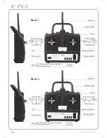
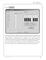
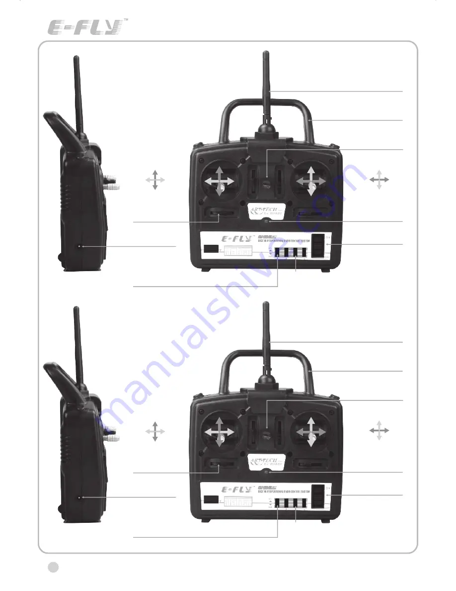
Trim
Hook
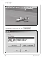
Trainer port
Servo
reverse
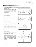
Elevator down
Rudder
left
Rudder
right
Elevator up
Power switch
Power indicator
Throttle Max
Aileron
left
Aileron
right
Throttle Min
Mode 1
Antenna
Carrying bar
NOR: normal mode
MIX: delta-wing or V type tail-wing mode
Model
Trim
Hook
Trainer port
Servo
reverse
Power switch
Power indicator
Antenna
Carrying bar
NOR: normal mode
MIX: delta-wing or V type tail-wing mode
Model
Mode 2
Rudder
left
Rudder
right
Throttle Max
Throttle Min
Elevator down
Elevator up
Aileron
left
Aileron
right
CERTIFICATION
We offer 35Mhz,
41Mhz and 72Mhz transmitter. The
40Mhz or 41Mhz transmitter has CE certification and the 72Mhz transmitter has FCC
certification.
36Mhz, 40Mhz,
35Mhz, 36Mhz,
CERTIFICATION
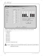
1.
2.
3.
4.
5.
6.
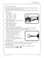
Pitch
Undercarriage
Rudder
Throttle
Servos
Black
Red
White
Elevator
Aileron
Operating voltage: 4.5V-6.5V
Current drain: 10mA
Number of channels: 6CH
System: FM(PPM) Single conversion
Sensitivity: 1V
Weight: 15g
Size(L x W x H): 47mm x 24mm x 12mm
Range(Height): 500m
Range(Distance): 400m
Adjacent channel rejection: -65dBm 16kHz
Available 35MHz receiver is compatible with JR transmitter, 40 Mhz
receiver is compatible with JR transmitter 72 Mhz receiver is compatible
Futaba transmitter.
Caution: When you plug the servo cable into the receiver, the black wire of
the servo cable should be nearest to the outside of the receiver box.
SERVO
We offer 6gram, 9gram and 17gram servos for selection. We offer 3 servos
in one package.
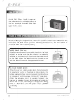
CRYSTAL
The crystal is located on the side of the receiver.
Output / battery connector
Aileron servo (Ch1) Elevator servo (Ch2)
Throttle servo (Ch3) Rudder servo (Ch4)
MANUAL FOR BRUSHED ESC
Features
:
Can control the motor run deasil and anti-clockwise.
Full proportional liner.
Auto cut-off for low voltage.
Signal loss protection: while no signal received, the ESC will auto cut-off
In order not to hurt anyone due to out of control.
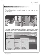
Assembling
:
1.Turn the transmitter on and push the throttle into minimum.
2.Plug the signal wire to the receiver and make sure all is correct.
3.Connect the battery and ESC and pay attention to the polarity, or that can
cause the damage to ESC. If there is the sound like
“
beep
”
, that means
everything is ok. If not, please check whether is ok, like the wire connection,
battery and the position of throttle.
4.After the Beep sound is over, you can start the motor by moving the throttle.
5.If the motor runs in the opposite direction as what you want, you can change
the connector of motor.
6.The connections between motor and ESC should be well protected, or that can
cause the damage to ESC
7.Please use this ESC under the working currency.
8.When the battery voltage is under the safety level or there is signal received,
ESC will auto cut off the supply for motor.
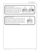
Signal connector for receiver
:
white
:
Signal wire
Red: positive
Black: negative
Battery connector
Connector
for motor
Specifications
:
30A
Input voltage:5V~14.4V
Output currency:30A/50A (Max)
BEC:5V/1A
Auto cut-off voltage:5V
Starting: throttle in min
(Starting point:1.0-1.5ms)
Dimension:21 x 32 x 10mm
Weight:15g


