background image

OPERATION 

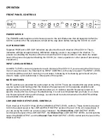
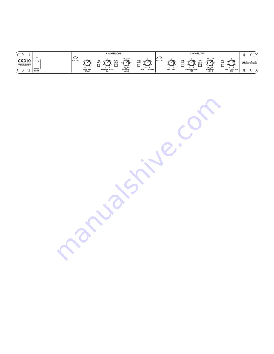
FRONT PANEL CONTROLS 


POWER SWITCH 

The POWER switch applies and removes power to the unit. Make sure that all equipment after the 

CX310 is either off or the outputs are turned all the way down before turning the CX310 on or off. 

CLIP INDICATORS 

Separate HIGH and LOW CLIP indicators are provided for each channel of the CX310. These 

indicators will light at approximately 3dB before clipping occurs in any stage of the channel. To 

prevent overloading the channel, either turn down the CX310 input control or turn down the output 

level of the piece of equipment feeding the CX310 (i.e. mixer, equalizer or other piece of processing 

equipment.). 

INPUT LEVEL CONTROLS 

An INPUT LEVEL control is provided on each channel of the CX310. If you are using the CX310 as a 

mono 3-way crossover, the Channel One INPUT CONTROL is the only one used. The INPUT LEVEL 

control should be set at its 0 marking in most cases. Increasing or decreasing gain should only be 

done to make up for deficiencies in other parts of the system. 

MUTE SWITCHES 

MUTE switches are provided for each output on the CX310. These are intended for use when setting 

up your system and testing either the crossover frequency point or the separate amplifiers and 

speakers they are feeding. These switches allow you to isolate a specific frequency output on a 

specific channel for fine-tuning or troubleshooting. It is not recommended that you mute or un-mute 

any frequency band during normal usage. Levels should be turned down when the MUTE switches 

are activated or de-activated. 

LOW AND HIGH OUTPUT LEVEL CONTROLS 

Each channel of the CX310 has LOW and HIGH OUTPUT LEVEL controls. These controls are used 

to trim the output levels to the LOW and HIGH OUTPUT jacks on the rear of the unit, respectively. If 

you are using the CX310 as a mono 3-way crossover, the 

Channel One

 LOW OUTPUT LEVEL 

control sets the level of the LOW OUTPUT, the 

Channel Two

 LOW OUTPUT LEVEL control sets the 

level of the MID OUTPUT, and the 

Channel Two

 HIGH OUTPUT LEVEL control sets the level of the 

HIGH OUTPUT. 

Summary of Contents for CX310

Page 1: ...CX310 Stereo 2 Way Mono 3 Way Active Crossover USER S GUIDE...

Page 2: ...n or against Grounding Do not defeat the grounding and polarization means of the power cord plug Do not remove or tamper with the ground connection on the power cord Moisture To reduce the risk of fir...

Page 3: ...Switch 6 Clip Indicators 6 Input Level Controls 6 Mute Switches 6 Low And High Output Level Controls 6 Crossover Frequency Controls And Range Switches 7 REAR PANEL CONNECTORS and CONTROLS 7 XLR Jacks...

Page 4: ...rovided for varying the crossover frequency from the standard 80Hz 920Hz to 800Hz 9200Hz Front panel output mute switches are provided for each individual output to ease system setup The rear panel fe...

Page 5: ...s are active balanced although the 1 4 phone jack connections can easily be converted to unbalanced operation by using two conductor phone plugs Inserting a plug into a 1 4 jack disconnects the associ...

Page 6: ...decreasing gain should only be done to make up for deficiencies in other parts of the system MUTE SWITCHES MUTE switches are provided for each output on the CX310 These are intended for use when sett...

Page 7: ...point In this case the Channel One RANGE switch will most commonly be used in the out position 80Hz 920Hz while the Channel Two RANGE switch will most commonly be used in the in position 800Hz 9 2kHz...

Page 8: ...rossover is the last piece of equipment in the signal chain before the power amplifiers Signal flow is as follows Mixer Equalizer Crossover Power Amplifier Speaker Cabinets Sometimes a limiter is plac...

Page 9: ...This warranty does not apply in the event of misuse or abuse of the product or as a result of unauthorized alterations or repairs This warranty is void if the serial number is altered defaced or remo...

Page 10: ...the website 3 If you are returning the unit for service pack the unit in its original carton or a reasonable substitute The original packaging may not be suitable as a shipping carton so consider putt...

Page 11: ...Level 13dBu Maximum Output Level 21dBu Total Harmonic Distortion THD 0 05 20Hz 20kHz Maximum Gain 4dB Power Requirements 105 120V AC 50 60hz 3VA USA Export units configured for country of destination...

Page 12: ...12 www artproaudio com E mail support artproaudio com 2010 Applied Research Technology CX310 V1 1...

Reviews:

Related manuals for CX310