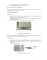
40
6.3. B3D BM
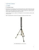
B3D BM Recognition Unit package includes 3D Camera, B3D BM Pole and monitor. Recognition Unit
should be assembled as follows. Please note that Recognition should not be powered on during
assembly.
6.3.1. Pole set up
The B3D BM Recognition Unit is meant to be installed on the floor. There are no special requirements of
the floor material, however, it should provide fixture strong enough to avoid Recognition Unit’s
wobbling, rocking and collapsing. Please note that Recognition Unit should not be powered on during
any described procedure.
B3D BM
Pole’s installation procedure:
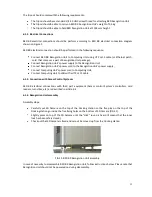
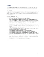
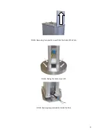
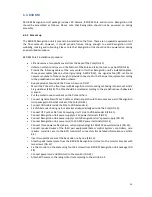
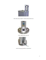
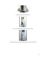
Lift and remove two plastic covers from the back of the Pole (FIG 45)
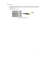
Unfasten metal round cover on the bottom of the Pole and take the cover up and off (FIG 46)
Provide the
following cables at the very center of further Recognition Unit’s installation place:
three power cables (phase, null and grounding, AWG 28-12), one signal cable (UTP cat.5) and
necessary number of wires enough to provide connection to the third part equipment according
to the predefined user installation scheme.
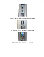
Run prepared cables inside the Pole as shown on FIG 47.
Mount the Pole at the floor level with Recognition Unit mounting set taking into account article
5.4 guidelines (FIG 48). The Pole should be oriented according to the predefined user behavioral
scenario.
Put the metal round cover back on the Pole and fix it.
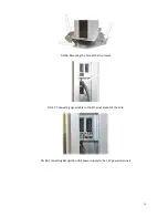
Connect signal cable (UTP cat.5 cable or Ethernet patch-cord that comes as a part of Recognition
Unit package) to Ethernet socket of the Pole (FIG 49)
Connect VGA cable inside the Pole to VGA Extender R.
Fix VGA Extender R using nylon cable ties and special ledges inside the Pole (FIG 50).
Connect UTP cat.5 cable from Computing Unit’s Side
to VGA Extender R (FIG 51).
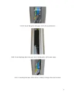
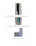
Connect Recognition Unit power supply to 12V power terminals (FIG 52)
Connect Recognition Unit power supply
cord to Recognition Unit’s power supply (FIG
53)
Connect Recognition Unit power cord to 100-220V power terminals (FIG 54)
Connect three power cables (phase, null and grounding) to 100-220V power terminals (FIG 55).
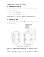
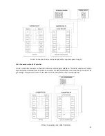
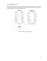
Connect required wires of the third part equipment (Access control System’s controllers, card
readers, turnstiles, etc.) to the B3D
controller’s
connectors (for detailed information see article
6.4)
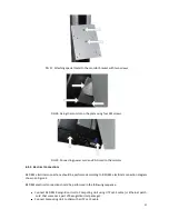
Insert two plastic covers at the back side one by one (FIG 56).
Attach special metal plate from the B3D BM Recognition Unit set to the monitor bracket with
two screws (FIG 57)
Fix the monitor on the plate using four M4 screws from B3D BM Recognition Unit package (FIG
58)
Connect power cord and VGA cord to the monitor (FIG 59)
Attach 3D Camera to the recognition Unit according to the article 6.2.4.

