1
Handling the Servomotor
Calibration and Setting Connector Numbers
Attaching Number Stickers
Orientation
1
2
The photo to the right shows the
servomotor facing you. There are two shafts,
the one with the wider space is the drive
shaft and the one with the narrower space
is the movable shaft.
★ When turning the drive shaft by hand, do
so very slowly and gently.
Excessive pressure when turning may
cause damage to the servomotor.
Before building your robot, read
6. Using Servomotors
in the
Studuino
Icon Programming Environment Guide
(download from
http://www.artec-kk.co.jp/artecrobo/) for instructions on how to
calibrate your servomotor.
Building your robot without calibrating your servomotor may cause
damage or improper functionality.
★ Do not change the connector or the servomotor after calibration.
Servomotor calibrations are unique to each servomotor.
After calibration, we recommend putting a sticker on the connector
used for the servomotor so it can be easily identified.
Wider
(drive shaft)
Narrower
(movable shaft)
2
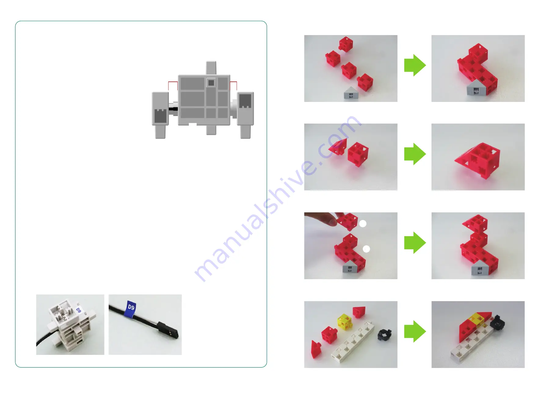
① Assemble the blocks as shown in the picture.
② Assemble the blocks as shown in the picture.
③ Attach part ② to part ① as shown.
④ Assemble the blocks as shown in the picture.
②
②
①
①


