6
IL6000 Chassis Installation and Operations Manual
IL6000 Chassis
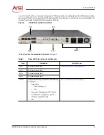
ILM121 Assembly Overview
The IL6000 chassis includes the integrated ILM121 assembly, which includes management ports for accessing
IL Manager, two AC power supplies, and a ventilation fan. The chassis can function using a single power supply
or you can use both power supplies for increased system availability. The power supplies provide limited load
sharing when both power connectors are used (see the
“Cabling the IL6000 Power Supplies” section on page
).
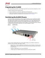
The fan provides ventilation for the chassis components and installed function modules (see the
the IL6000 Chassis” section on page 7
).
The ILM121 assembly includes voltage, temperature, and cooling fan alarms.
Figure 3.
ILM121 Assembly Components
describes the components called out in
.
Table 3.
ILM121 Assembly Components
Item
Description
For details, see . . .
1
EMS - Status LED for IL Manager.
Powering Up and Monitoring the IL6000 (page 14)
2
OK - Chassis status LED.
3
RST - Chassis reset switch.
Using the IL6000 Reset Switch (page 17)
4
MGMT - Ethernet management ports (2).
Information About Using IL Manager (page 16)
5
PSB - AC power supply B.
Cabling the IL6000 Power Supplies (page 12)
6
PSA - AC power supply A.
7
Chassis ventilation fan.
Ventilating the IL6000 Chassis (page 7)
Required Installation Tools and Equipment
To install the IL6000 as a rack-mounted or wall-mounted unit, you need:
•
Phillips head screwdriver to reposition the chassis mounting ears (optional)
•
Four rack mounting screws and matching screw driver (not supplied)
1 2
3
4
5
6
7
Summary of Contents for InfinityLink IL6000
Page 1: ...WWW ARTEL COM Manual Installation and Operations Manual INFINITYLINK IL6000 Chassis...
Page 2: ...ii IL6000 Chassis Installation and Operations Manual...
Page 4: ...iv IL6000 Chassis Installation and Operations Manual...
Page 11: ...IL6000 Chassis Installation and Operations Manual xi...
Page 31: ...18 IL6000 Chassis Installation and Operations Manual...
Page 33: ...Index Index 2 IL6000 Chassis Installation and Operations Manual...
Page 34: ......

