I
SKYDRO
designed by Ross Lovegrove
Apparecchio in CL I IP20
AVVERTENZE
Prima di ogni operazione sull’apparecchio, disinserire la tensione di rete.
Usare esclusivamente le lampadine del tipo e potenza indicati nei dati di targa.
ARTEMIDE S.p.a. non si assume alcuna responsabilità per prodotti modificati senza previa autorizzazione.
ATTENZIONE
: Per procedere all’installazione dell’apparecchio in modo corretto sono necessarie almeno
due persone.
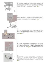
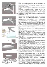
In caso di montaggio su supporti mobili (es. controsoffitti), verificare attentamente che gli stessi assicurino
adeguato contrasto prima di seguire i passi descritti in figg. 21-22.
ISTRUZIONI DI MONTAGGIO MODULO SINGOLO
Importante!
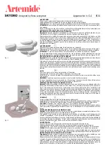
Prima di procedere all’installazione, verificare che lo spazio di soffitto delimitato da una
circonferenza di 1m di raggio, centrata sul punto luce, sia libero da ostacoli (fig.2).
Questo consente di orientare la composizione a proprio piacimento senza rischi di interferenza con altri
oggetti. Qualora lo spazio libero sia inferiore, l’apparecchio può essere installato uguamente, ma solo
in determinate posizioni, da verificare molto attentamente prima di forare il soffitto. Per garantire il
corretto montaggio dei sassi cromati è necessario che le strutture installate siano in piano. Compensare
eventuali avvallamenti inserendo spessori tra la struttura ed il plafone nella sola zona delle bugne di
alloggiamento dei tasselli.
fig. 1
fig. 2
AVERTISSEMENT
Déconnecter la tension de réseau avant toute opération sur l’appareil.
Employer exclusivement les ampoules du type et de la puissance indiqués sur la plaque de l’appareil.
ARTEMIDE S.p.a. décline toute responsabilité pour les produits modifiés sans autorisation préalable.
ATTENTION
Au moins deux personnes sont nécessaires pour installer correctement l’appareil.
En cas d’assemblage sur des supports mobiles (ex. faux plafonds), vérifier attentivement que ces
supports assurent un contraste adéquat avant de suivre les pas décrits dans les figures 21-22.
ISTRUCTIONS DE MONTAGE MODULE UNIQUE
Important!
Avant de procéder à l’installation, vérifier que l’espace de plafond délimité par une circonférence
de 1m de rayon, centrée sur le point de lumière, soit libre d’obstacles (fig.2).
Cela permet d’orienter la composition comme on désire sans risques d’interférence avec d’autres objets. Si
l’espace libre est inférieur, l’appareil peut être installé mais seulement dans des positions déterminées qui
doivent être vérifiées très attentivement avant de percer le plafond. Pour assembler correctement les pierres
chromées il faut que les structures installées soient nivelées parfaitement. Compenser les dénivellations
éventuelles en insérant des cales entre la structure et le plafond seulement dans la zone des bossages des
chevilles.
NOTE
Prior to any work on the fixture always switch off the mains.
Only use bulbs of the type and wattage indicated on the rating plate.
ARTEMIDE S.p.a. does not shoulder any responsibilities for products which are modified without prior
authorisation.
WARNING
At least two people are required in order to install the fixture correctly.
In case of assembly on moving supports (i.e. false ceiling), check carefully that these latters ensure
suitable contrast before following the steps described in figures 21-22.
ASSEMBLY INSTRUCTIONS FOR SINGLE MODULE
Important!
Before proceeding with the installation, make sure that there are no obstacles within the
ceiling area delimited by a circumference with a radius of 1m, centered with respect to the light point
(fig.2). This allows you to position your composition as you desire without the risk of interfering with
other objects. In case the free space is smaller, the fixture can be installed all the same, but only in specific
positions, which must be checked very carefully before drilling the ceiling. To ensure the correct assembly
of the chromium-plated stones, the installed structures must be perfectly levelled. Compensate for
possible depressions by inserting some shims between the structure and the ceiling only in the area of
the seating hollows for the screw anchors.
VORSICHT
Vor jedem Eingriff an dem Gerät die Netzspannung unterbrechen.
Ausschließlich Lampen verwenden, die dem auf dem Geräteschild angegebenen Typ und Wert entsprechen.
ARTEMIDE S.p.a. nimmt keine Verantwortung für ohne Vorgenehmigung geänderte Produkte an.
ACHTUNG
Mindestens zwei Personen sind nötig, um das Gerät korrekt zu installieren.
Im Fall von Montage auf bewegliche Unterlagen (z. B. Zwischendecken) prüfen Sie aufmerksam, daß sie
einen geeigneten Gegensatz gewährleisten, bevor die in Abbildungen 21-22 beschriebenen Schritte
folgen.
MONTAGEANWEISUNGEN DES EINZELMODULS
Wichtig!
Vor der Installation prüfen, ob der durch eine um das Lichtpunkt zentrierte Kreislinie mit 1 m-
Radius begrenzte Deckenraum ohne Hindernisse ist (Abb.2).
Das gestattet die Ausrichtung der Kombination nach Belieben ohne Risiko einer Überlagerung mit
anderen Gegenständen. Wenn der freie Raum kleiner ist, kann das Gerät dennoch installiert werden,
doch nur in bestimmten Positionen, die vor der Durchbohrung der Decke zu prüfen sind. Zur Gewährleistung
der richtigen Montage der farblichen “Steine” sollen die installierten Struktur eben sein. Zwischenstücke
zwischen der Struktur und der Decke nur in der Zone der Sitze der Dübel.
ADVERTENCIA
Antes de efectuar cualquier operación sobre el aparato desconectar la tensión de red.
Utilizar exclusivamente las bombillas del tipo y potencia indicada en la placa de identificación.
ARTEMIDE S.p.a. no se asume ninguna responsabilidad ante productos modificados sin autorización.
CUIDADO
Para instalar el aparato del modo correcto, se necesitan por lo menos dos personas.
En caso de montaje en soportes móviles (ej. falsos techos), controlar cuidadosamente que los mismos
puedan soportar el peso de la lámpara antes de efectuar las operaciones descritas en las figuras 21-22.
INSTRUCCIONES DE MONTAJE MÓDULO ÚNICO
¡Importante!
Antes de efectuar la instalación, cerciorarse de que en el espacio de techo limitado por una
circunferencia de 1m de radio, centrada en el punto de luz, no haya obstáculos (fig.2).
Esto permite orientar la composición a su gusto sin chocar contra otros objetos. Si el espacio libre es inferior,
el aparato se puede instalar igualmente, pero sólo en algunas posiciones a verificar muy cuidadosamente
antes de perforar el techo. Para garantizar el montaje correcto de las piedras cromadas, las estructuras
instaladas deben estar perfectamente niveladas. Compensar desniveles eventuales introduciendo piezas de
llenado entre la estructura y el techo sólo en la zona de las cavidades donde se ponen los tacos.
F
EN
D
E


