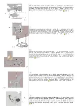
Allentare i pomoli
C
ed aprire i 5 chiavistelli di fissaggio delle strutture laterali (fig. 8).
Posizionare una struttura laterale negli appositi scassi della struttura centrale e chiudere i
chiavistelli avvitando i pomoli (fig. 9).
Segnare la posizione dei tasselli (fig. 10). Smontare la struttura, forare, rimontare serrando
bene tutti i pomoli e fissare con i tasselli (fig. 11). Eseguire le medesime operazioni anche
per le altre strutture laterali.
fig. 8
fig. 9
~
~
C
C
fig. 10
fig. 11
I
F
EN
D
E
Desserrer les poignées
C
et ouvrir les 5 loquets de fixation des structures latérales (fig. 8).
Positionner une structure latérale dans les ouvertures adéquates de la structure centrale et
fermer les loquets en vissant les poignées (fig. 9).
Marquer la position des chevilles (fig. 10). Désassembler la structure, percer, réassembler
en serrant bien toutes les poignées et fixer à l’aide des chevilles (fig. 11). Effectuer les
mêmes opérations pour les autres structures latérales aussi.
Loosen knobs
C
and open the 5 lock bolts of the side structures (fig. 8). Position a side
structure in the proper openings of the central structure and close the locking bolts by
screwing knobs (fig. 9).
Mark the position of the screw anchors (fig. 10). Disassemble the structure, drill, assemble
again by tighening all the knobs and fix by means of the screw anchors (fig. 11). Carry out
the same operations also for the other side structures.
Die Knöpfe
C
lockern und die 5 Riegel zur Befestigung der seitlichen Strukturen (Abb. 8)
öffnen. Die seitliche Struktur in den dazu bestimmten Öffnungen der mittleren Struktur
positionieren und die Knöpfe (Abb. 9) anschrauben.
Die Position der Dübel (Abb. 10) markieren. Die Struktur ausbauen, durchbohren und
wieder montieren; alle Knöpfe spannen und mit den Dübeln (Abb. 11) befestigen. Dieselben
Verfahren auch für die anderen seitlichen Strukturen ausführen.
Aflojar los elementos esféricos
C
y abrir los 5 pasadores de fijación laterales (fig. 8). Poner
una estructura lateral en las aberturas adecuadas de la estructura central y cerrar los
pasadores atornillando los elementos esféricos (fig. 9).
Marcar la posición de los tacos (fig. 10). Desmontar la estructura, perforar, montar
nuevamente apretando todos los elementos esféricos y fijar con los tacos (fig. 11). Efectuar
las mismas operaciones también para las demás estructuras laterales.


