background image

SharpStreamer™ Pro Mini PCIE-7210-1 Installation and Use (6806800U78A)

About this Manual

14

About this Manual

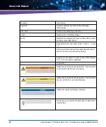
Reference

Used for references and for table and figure 
descriptions

File > Exit

Notation for selecting a submenu

<text>

Notation for  variables and keys

[text]

Notation for software buttons to click on the screen 
and parameter description

...

Repeated item for example node 1, node 2, ..., node 
12

.
.
.

Omission of information from example/command 
that is not necessary at the time being.

..

Ranges, for example: 0..4 means one of the integers 
0,1,2,3, and 4 (used in registers).

|

Logical OR.

Indicates a hazardous situation which, if not avoided, 
could result in death or serious injury.

Indicates a hazardous situation which, if not avoided, 
may result in minor or moderate injury 

Indicates a property damage message.

No danger encountered. Pay attention to important 
information.

Notation

Description

Summary of Contents for 6806800U78A

Page 1: ...SharpStreamer Pro Mini PCIE 7210 1 Installation and Use P N 6806800U78A December 2017 ...

Page 2: ...eferenced in another document as a URL to an Artesyn website The text itself may not be published commercially in print or electronic form edited translated or otherwise altered without the permission of Artesyn It is possible that this publication may contain reference to or information about Artesyn products machines and programs programming or services that are not available in your country Suc...

Page 3: ... Unpacking and Inspecting Card 31 2 2 Environmental Thermal and Power Requirements 32 2 2 1 Environmental and Thermal Requirements 32 2 2 2 Power Requirements 33 2 3 Precautions 34 2 3 1 ESD Prevention 35 2 4 PCIE 7210 1 Card Installation and Removal 36 2 4 1 PCIE 7210 1 Card Installation 36 2 4 2 PCIE 7210 1 Card Removal 37 3 Functional Description 39 3 1 CPU Complex 40 3 1 1 Intel Skylake H Proc...

Page 4: ... 45 3 10 Reset Management 46 3 11 JTAG 46 4 Controls Indicators and Connectors 47 4 1 Connectors 47 4 1 1 PCIE 7210 1 Faceplate View 47 4 1 2 Edge Connector 48 4 1 3 CPLD Programmer JTAG Port 50 4 1 4 ATX Power Connector 51 4 2 LEDs 52 4 2 1 Debug LEDs 52 4 2 2 Port Good LEDs 54 4 2 3 I210 LEDs 55 4 2 4 I219 LEDs 56 4 2 5 User LED 57 4 3 Controls 59 4 4 Switch Settings 60 5 PCIE Software 63 5 1 So...

Page 5: ...73 5 4 3 3 Installation 73 5 4 3 4 Login Details 75 5 4 4 Rack Mount Server 76 5 5 Network Configuration 77 5 6 pcie7210 1 tool sh 77 5 6 1 Change Mac address of PLX vNIC devices 77 5 6 2 Usage 78 5 6 2 1 Skylake H 79 6 Firmware Upgrade 81 6 1 BIOS Upgrade 81 6 2 CPLD Firmware Upgrade 83 A Programming 85 A 1 Programming PEX9716 eeprom with Base Mode using PlxCm on Quark 85 A 1 1 Pre requisites 85 ...

Page 6: ...SharpStreamer Pro Mini PCIE 7210 1 Installation and Use 6806800U78A 6 Contents A 3 2 Instructions 89 B Related Documentation 91 B 1 Artesyn Embedded Technologies Embedded Computing Documentation 91 ...

Page 7: ... 6 PCH Sleep Status 53 Table 4 7 PCH Power Status 53 Table 4 8 SPI Program Status 53 Table 4 9 Port Good LEDs Status 54 Table 4 10 On Off state of a Port Good LED 55 Table 4 11 I210 LEDs Status 56 Table 4 12 I219 LEDs Status 57 Table 4 14 User LED Status 58 Table 4 13 User LED Color Indication 58 Table 4 15 Switch Position Indication based on Host Server 60 Table 5 1 Package Information 63 Table 5...

Page 8: ...SharpStreamer Pro Mini PCIE 7210 1 Installation and Use 6806800U78A 8 List of Tables ...

Page 9: ...cation of Temperature and power sensors Secondary Side 45 Figure 4 1 PCIE 7210 1 Faceplate 47 Figure 4 2 Location of Debug LEDs 52 Figure 4 3 Location of Port Good LEDs 54 Figure 4 4 Location of I210 LEDs 55 Figure 4 5 Location I219 LEDs 56 Figure 4 6 Location User LED 57 Figure 4 7 S3 Reset Button 59 Figure 4 8 Location of Switches 60 Figure 4 9 Switch Settings MaxCore MC3000 and MaxCore MC1000 I...

Page 10: ...SharpStreamer Pro Mini PCIE 7210 1 Installation and Use 6806800U78A 10 List of Figures ...

Page 11: ...ct environmental and power requirements and installation and removal instructions Functional Description on page 39 provides information about the functional blocks in the SharpStreamer Pro Mini PCIE 7210 1 card block diagram Controls Indicators and Connectors on page 47 provides information about the controls indicators connectors and pin assignments associated with the PCIE 7210 1 card PCIESoftw...

Page 12: ... Memory Access DMI Direct Media Interface DPC DIMM Per Channel FCU Firmware Command line Utility FRU Field Replaceable Unit GPU Graphics Processing Unit HEVC High Efficiency Video Coding I2C Inter Integrated Circuit JTAG Joint Test Action Group LPC Low Pin Count MAC Media Access Control mCPU Management CPU MDI Media Dependent Interface NIC Network Interface Card OTT Over the Top PCH Platform Contr...

Page 13: ... Test Data Input TDO Test Data Output TFTP Trivial File Transfer Protocol UEFI Unified Extensible Firmware Interface VNC Virtual Network Computing vNIC virtual NIC XDP eXtended Debug Port Abbreviation Definition Notation Description 0x00000000 Typical notation for hexadecimal numbers digits are 0 through F for example used for addresses and offsets 0b0000 Same for binary numbers digits are 0 and 1...

Page 14: ...iption Repeated item for example node 1 node 2 node 12 Omission of information from example command that is not necessary at the time being Ranges for example 0 4 means one of the integers 0 1 2 3 and 4 used in registers Logical OR Indicates a hazardous situation which if not avoided could result in death or serious injury Indicates a hazardous situation which if not avoided may result in minor or...

Page 15: ...reamer Pro Mini PCIE 7210 1 Installation and Use 6806800U78A 15 Summary of Changes This manual has been revised and replaces all prior editions Part Number Publication Date Description 6806800U78A December 2017 Initial version ...

Page 16: ...SharpStreamer Pro Mini PCIE 7210 1 Installation and Use 6806800U78A About this Manual 16 About this Manual ...

Page 17: ...l trained by Artesyn or persons qualified in electronics or electrical engineering are authorized to install remove or maintain the product The information given in this manual is meant to complete the knowledge of a specialist and must not be used as replacement for qualified personnel Keep away from live circuits inside the equipment Operating personnel must not remove equipment covers Only fact...

Page 18: ... frequency emissions compliance is maintained Operation Product Damage Surface of the Product High humidity and condensation on the product surface causes short circuits Do not operate the product outside the specified environmental limits Make sure the product is completely dry and there is no moisture on any surface before applying power Overheating and Product Damage Operating the product witho...

Page 19: ...hing the product or electronic components make sure that your are working in an ESD safe environment Product Damage Incorrect installation of the product can cause damage of the product Only use appropriate tools when installing removing the product to avoid damage deformation to the card and or PCB Environment Always dispose equipment that is finally taken out of operation according to your count...

Page 20: ...SharpStreamer Pro Mini PCIE 7210 1 Installation and Use 6806800U78A Safety Notes 20 ...

Page 21: ...mationen benötigen sollten wenden Sie sich bitte an die für Sie zuständige Geschäftsstelle von Artesyn Das System erfüllt die für die Industrie geforderten Sicherheitsvorschriften und darf ausschließlich für Anwendungen in der Telekommunikationsindustrie und im Zusammenhang mit Industriesteuerungen verwendet werden Einbau Wartung und Betrieb dürfen nur von durch Artesyn ausgebildetem oder im Berei...

Page 22: ...ührt werden können dazu führen dass der Anwender die Genehmigung zum Betrieb des Produktes verliert Boardprodukte werden in einem repräsentativen System getestet um zu zeigen dass das Board den oben aufgeführten EMV Richtlinien entspricht Eine ordnungsgemässe Installation in einem System welches die EMV Richtlinien erfüllt stellt sicher dass das Produkt gemäss den EMV Richtlinien betrieben wird Ve...

Page 23: ... die FunktionsfähigkeitmußdurcheinenqualifiziertenReparaturdienstwiederhergestelltwerden Installation Beschädigung von Schaltkreisen Elektrostatische Entladung und unsachgemäßer Ein und Ausbau des Produktes kannSchaltkreise beschädigen oder ihre Lebensdauer verkürzen Bevor Sie das Produkt oder elektronische Komponenten berühren vergewissern Sie sich daßSie in einem ESD geschützten Bereich arbeiten...

Page 24: ...SharpStreamer Pro Mini PCIE 7210 1 Installation and Use 6806800U78A Sicherheitshinweise 24 ...

Page 25: ...sily deployable in off the shelf platforms The PCIE 7210 1 CPU is capable of up to eight 8 streams of 1080p30 H 265 HEVC transcodes or four 4 streams of 1080p60 H 265 HEVC transcodes The CPU offers one 1 4Kp60 HEVC or up to two 2 4Kp30 HECV transcodes The SharpStreamer Pro Mini PCIE 7210 1 solution is easily deployable portable and does not constrain operators to a single type of equipment to mone...

Page 26: ...Root Input Output Virtualization SR IOV or multifunction devices and to enable multiple hosts to reside on a single PCIe based network using standard PCIe enumeration a capability not previously available on PCIe devices The hosts communicate through Ethernet like Direct Memory Access DMA and do so using standard hosts end points and application software In standard or RMS servers the PEX9716 devi...

Page 27: ...pStreamer Pro Mini PCIE 7210 1 Installation and Use 6806800U78A 27 Figure 1 1 and Figure 1 2 depicts top and bottom views of the PCIE 7210 1 card Figure 1 1 Mechanical Layout Top View 167 65 mm 111 15 mm Edge Connector ...

Page 28: ... 3 Software Overview The software for the PCIE 7210 1 card is delivered in the form of integrated ISO image which contains CentOS based Linux OS necessary binaries utilities tools to enable PCIE 7210 1 card functionality for media transcoding and firmware upgrades Figure 1 2 Bottom View ...

Page 29: ...A Radiated Emissions 47CFR15 FCC ANSI C63 4 EN 55032 CISPR 32 Class A ICES 003 Class A Conducted Emissions EN 300 386 v1 6 1 2012 EN 61000 4 2 2009 ESD EN 300 386 v1 6 1 2012 EN 61000 4 3 2010 Radiated Immunity EN 300 386 v1 6 1 2012 EN 61000 4 4 2012 EFT EN 300 386 v1 6 1 2012 EN 61000 4 11 2004 Voltage Dips and Interrupts Table 1 2 Ordering Information Part Number Description PCIE 7210 1 SharpSt...

Page 30: ...Introduction SharpStreamer Pro Mini PCIE 7210 1 Installation and Use 6806800U78A 30 ...

Page 31: ...nspection To inspect the shipment perform the following steps 1 Verify that you have received all items of your shipment One SharpStreamer Pro Mini PCIE 7210 1 card One printed copy of Quick Start Guide One printed copy of Safety Notes Summary Any optional items ordered 2 Check your shipment and report any damage or differences to the Contact Center at RMASupport ec Artesyn com Damage of Circuits ...

Page 32: ... Thermal Requirements Make sure the card is thoroughly inspected before shipment If any damage has occurred during transportation please contact our Contact Center immediately Operating temperatures refer to the temperature of the incoming air passing across the card and out of the faceplate and not the temperature of the components Card Damage High humidity and condensation on the card surface ca...

Page 33: ...3117 feet 40 C to 70 C Minimum Airflow Reference to sea level 600 LFM 3 m Sec Temperature Change 20 C Hr 68 F h 20 C Hr 68 F h Relative Humidity 5 to 85 relative humidity with 29 C 84 2 F maximum dew point 5 to90 Non Condensingbutnot to exceed 0 024 kg of water per kg of dry air Shock and Vibration 0 01 G s 5 to 200 Hz EN 300 019 2 2 Class T 2 3 Altitude 3048 m 12 000 m Table 2 2 Power Requirement...

Page 34: ...ot touch the circuit with bare hands The static electricity of the human body may damage the Electro Static Sensitive Devices ESSDs on the circuit Make sure that you wear an Electro Static Discharge ESD preventive wrist strap or antistatic glove to prevent the static electricity from hurting you or damaging the device Keep your personal objects such as your clothes away from the system To prevent ...

Page 35: ...e shelf Avoid moving as much as possible Movement gathers static electricity around you Do not touch the solder point pin or bare circuit Do not leave the device in the place where others can operate it Install the device at once after you take it out of the anti static package If you need to lay down the device place it back in the anti static package Do not lay the device on the shelf or cabinet...

Page 36: ...e 34 2 Remove the server cover Shipping the card along with a server is not recommended If you still need to ship the card along with the server ensure the card is properly secured in the server Check if necessary precautions were followed to keep the card resistive against wobbling Otherwise there are chances of card getting damaged For more information about securing the PCIe card in a server re...

Page 37: ...ake sure you are in an ESD safe environment 2 Power off the server disconnect the server from the electrical outlet and peripherals and remove any cables connected to the card 3 Remove the screw holding the front panel bracket and gently pull the PCIE 7210 1 card from the slot 4 Close the cover of the server Make sure that the card has enough air flow after closing the system with the cover Refer ...

Page 38: ...Hardware Preparation and Installation SharpStreamer Pro Mini PCIE 7210 1 Installation and Use 6806800U78A 38 ...

Page 39: ... SharpStreamer Pro Mini PCIE 7210 1 Block Diagram SKYLAKE PCH CPU SKYLAKE H Micro SD slot Micro USB Port COM Port USB 2 0 SMBUS DDR4 SODIMM DDR4 SODIMM POWER Sensor DMI 2 0x4 2133MT S Temp Sensor I2C0 I219 Ext Phy PLX ExpressFabric Switch PCIe Gen3 x4 32Gbps PCIe edge connector Mechanical x8 electrical x4 PCIe Gen3 x4 32Gbps CPLD Intel QUARK SoC DD3 Memory PCIe Gen2 x1 12V 3 3V 3 3V Aux I210 Mac P...

Page 40: ... supports all the IO functions used in conjunction with Intel CPU 3 2 Intel Quark SoC device The Intel Quark SoC processor is the next generation secure low power Intel architecture for deeply embedded applications The SoC integrates the Intel Quark SoC Core and all the required hardware components to run off the shelf operating systems and to leverage the vast x86 software ecosystem The SoC proce...

Page 41: ...PCIe Gold Finger edge connector A voltage and current monitor circuit is provided on the 12 V bus to PCH This can be used to measure the power consumed by the card The edge connector provides 3 3 V supply to the CPLD 3 6 Interfaces This section provides the details of various interfaces used on the PCIE 7210 1 card to interconnect various blocks It also describes user interfaces available for exte...

Page 42: ... Channel DPC DDR3 Intel quark processor has one memory channel The channel of the processor is connected with DDR3 device USB2 0 One port of Skylake PCH USB port interfaced with front panel Micro USB connector for data transfer One port of Quark SoC processor USB port interfaced with front panel Micro USB connector for data transfer Media Dependent interface Media Dependent interface MDI is connec...

Page 43: ...ible for managing the boot process The boot process loads a boot image that is stored in 128 Mbit on board Serial Peripheral Interface SPI FLASH connected to Skylake H PCH device 3 7 Micro SD Slot Two Micro SD slots are available on each PCIE 7210 1 card One Micro SD slot J8 is connected to SKylake CPU and other slot J7 connected to Quark processor The Micro SD card slot in slot J8 can be used eit...

Page 44: ... on the Micro SD storage device If no boot record is found then the card tries to PXE boot from the server If this is not successful the processor reboots and tries the boot sequence again The boot sequence can be modified in the BIOS 3 8 Temperature Sensors A temperature sensor located at the center of the board is used to measure the board temperature It is connected to the PCH through the I2C i...

Page 45: ...tals One 24 MHz crystal to drive all the main buses and a 32 768 KHz crystal to drive the Real Time Clock RTC Processor clocks are driven from PCH device CPU has a dual channel memory each memory channel provides an 1066 67 MHz clock Quark processor takes 25 MHz clock as a reference clock and provides synchronous clock to PEX9716 and Ethernet devices Figure 3 3 Location of Temperature and power se...

Page 46: ... up the CPLD state machine drives the reset control to CPU during an induced reset from the front panel reset switch For more information about Reset button refer the section Controls on page 59 3 11 JTAG Joint Test Action Group JTAG pins are mapped to the CPLD JTAG programming pins CPLD programming port at connector P2 independent connector for CPLD E3 1578L v5 and PCH JTAG pins are connected to ...

Page 47: ...rmation on controls indicators and connectors associated with the PCIE 7210 1 card 4 1 Connectors 4 1 1 PCIE 7210 1 Faceplate View The following figure shows the faceplate view of the PCIE 7210 1 card Figure 4 1 PCIE 7210 1 Faceplate Push Button Reset USB2 0 Quark USB2 0 Skylake Console via USB 2 0 Quark Console via USB 2 0 Skylake Status LED ...

Page 48: ...V 12 Volt power 4 GND Ground GND Ground 5 CON_SMB_CLK SMBus clock JPCIE_JTAG _TCK PCIe Edge Test Clock TCK 6 CON_SMB_DAT SMBus data CPLD_TDI PCIe Edge Test Data Input TDI 7 GND Ground PCIE_SKL_T DO PCIe Edge Test Data Output TDO 8 3 3V 3 3 Volt power PCIE_JTAG_ TMS PCIe Edge Test Mode Select TMS 9 PCIE_JTAG_ TRST_N PCIE EDGE TRST L TRST TestReset resets the JTAG interface 3 3V 3 3 Volt power 10 PC...

Page 49: ...IE_G3_R X2_P_N Receiver Lane 2 Differential pair 26 GND Ground 27 PCIE_G3_TX3_ P_N Transmitter Lane 3 Differential pair GND Ground 28 GND Ground 29 GND Ground PCIE_G3_R X3_P_N Receiver Lane 3 Differential pair 30 RSVD Reserved 31 RSVD Reserved GND Ground 32 GND Ground RSVD Reserved 33 RSVD Reserved RSVD Reserved 34 RSVD Reserved GND Ground 35 GND Ground RSVD Reserved 36 GND Ground RSVD Reserved 37...

Page 50: ...ammed when it is powered with 3 3 V supply from the card edge connector The header pin out is shown in the below table 43 GND Ground RSVD Reserved 44 GND Ground RSVD Reserved 45 RSVD Reserved GND Ground 46 RSVD Reserved GND Ground 47 GND Ground RSVD Reserved 48 PCIE_EDGE_PR ESENT_X8 Hot Plug presence detect RSVD Reserved 49 GND Ground GND Ground Table 4 1 PCIE 7210 1 Card Edge Connector Pinout con...

Page 51: ... Pro Mini PCIE 7210 1 Installation and Use 6806800U78A 51 4 1 4 ATX Power Connector The 12 V ATX power connector is optionally provided on board Table 4 3 ATX Power Connector Pinout Pin Name 1 12V0_ATX 2 12V0_ATX 3 12V0_ATX 4 Ground 5 Ground 6 Ground ...

Page 52: ...ebug LEDs The following figure depicts location of debug LEDs D17 D16 D15 D14 D13 D12 D11 and D10 on the PCIE 7210 1 card Figure 4 2 Location of Debug LEDs Table 4 4 PEX9716 Power Status LED Representation Value Status D17 PEX9716 power is up and stable 0 LED will glow PEX9716 power is not up 1 LED will not glow Debug LEDs ...

Page 53: ...ep status 1 LED will not glow Table 4 7 PCH Power Status Powers Signal status Value D15 D14 D13 PCH_3V3_PWRGD FAIL 111 OFF OFF OFF PCH_1V0_PWRGD FAIL 001 ON ON OFF SKL_V2P5_PWRGD FAIL 010 ON OFF ON SKL_VDDQ_PWRGD FAIL 011 ON OFF OFF PCH_VCCST_PWRGD FAIL 100 OFF ON ON PCH_VCCSTG_PWRGD FAIL 101 OFF ON OFF SKL_VCCIO_PWRGD FAIL 110 OFF OFF ON All Power goods are stable PASS 000 ON ON ON Table 4 8 SPI ...

Page 54: ... Good LEDs D28 D29 D30 and D31 on the PCIE 7210 1 card Figure 4 3 Location of Port Good LEDs Table 4 9 Port Good LEDs Status LED Indication D28 Indicates status of link connected between Port 0 of PEX9716 and Quark SoC device D29 Indicates status of link connected between Port 1 of PEX9716 and PCIe slot D30 Indicates status of link connected between Port 2 of PEX9716 and I210 device D31 Indicates ...

Page 55: ...llowing figure depicts location of I210 LEDs D20 D22 and D7 Table 4 10 On Off state of a Port Good LED State LED Pattern Link is down Off Link is Up 2 5 GT s any negotiated Link width Blinking 512 ms On 512 ms Off 1 Hz Link is Up 5 0 GT s any negotiated Link width Blinking 256 ms On 256 ms Off 1 Hz Link is Up 8 0 GT s any negotiated Link width On Figure 4 4 Location of I210 LEDs i210 LEDs ...

Page 56: ... LEDs The following figure depicts location of I219 LEDs D34 D35 and D36 Table 4 11 I210 LEDs Status LED Indication D7 Indicates the Link up activity of I210 device D20 Indicates the 1000 Mbps Link activity of I210 device D22 Indicates the 100 Mbps Link activity of I210 device Figure 4 5 Location I219 LEDs i219 LEDs ...

Page 57: ... a user LED D21 displayed on the front panel It is a tricolor LED which indicates Red Green and Blue colors Table 4 12 I219 LEDs Status LED Indication D34 Indicates the Link up activity of I219 device D35 Indicates the 1000 Mbps Link activity of I219 device D36 Indicates the 100 Mbps Link activity of I219 device Figure 4 6 Location User LED User LED ...

Page 58: ... of Blue LED indicates mismatch of the switch setting S5 against PEX mode value detected Table 4 14 User LED Status LED Skylake Power Up PEX Mode Detect Register Written Verification against Switch S5 LED Output D21 No No No Red No Yes No Red No Yes Yes Red Blue Blinking Blue or Solid Blue Yes No No Red Green Yes Yes No Green Yes Yes Yes Green Blue Blinking Blue or Solid Blue VerificationagainstSw...

Page 59: ...SharpStreamer Pro Mini PCIE 7210 1 Installation and Use 6806800U78A 59 4 3 Controls The Reset button S3 is located on the faceplate of the PCIE 7210 1 card By pressing this button CPU on the card gets reset Figure 4 7 S3 Reset Button S3 ...

Page 60: ...s on the PCIE 7210 1 card Figure 4 8 Location of Switches Table 4 15 Switch Position Indication based on Host Server Switch MaxCore MC3000 MaxCore MC1000 IPC MaxCore PICO RMS Switch S5 Pin 1 Down PEX9716 in Base Mode Up PEX9716 in Fabric Mode Down PEX9716 in Base Mode Up PEX9716 in Fabric Mode Switch S5 Pin 2 Up SSC Disabled Up SSC Disabled Up SSC Disabled Down SSC Enabled ...

Page 61: ... Down PEX9716 Ref Clock from PCH Up PEX9716Ref Clock from Quark Down PEX9716 Ref Clock from PCH Up PEX9716 Ref Clock from Quark Switch S5 Pin 4 Down power control from BMC Up power control from Quark Up Auto power Up power control from Quark Figure 4 9 Switch Settings MaxCore MC3000 and MaxCore MC1000 IPC Table 4 15 Switch Position Indication based on Host Server continued Switch MaxCore MC3000 Ma...

Page 62: ...Controls Indicators and Connectors SharpStreamer Pro Mini PCIE 7210 1 Installation and Use 6806800U78A 62 Figure 4 10 MaxCore PICO Figure 4 11 Switch Settings RMS ...

Page 63: ...s designed to work with standard or RMS servers that is Dell R730 and Artesyn s MaxCore servers MC3000 and MC1000 IPC Based on the server in which the PCIE 7210 1card is plugged in the mode of operation of PEX9716 would differ In standard or RMS and MaxCore IPC server PEX9716 would operate in fabric mode and in MaxCore MC3000 server PEX9716 would operate in base mode Users are requested to ensure ...

Page 64: ...Dell R730 and MaxCore MC1000 IPC PEX9716 should be configured in fabric mode Refer to section Programming PEX9716 eeprom with Fabric Mode using PlxCm on Skylake on page 87 5 3 Prerequisites for Card Operation Following are some of the configuration settings to be considered for the card to be functional in standard or RMS MaxCore MC3000 MaxCore MC1000 IPC in which card is plugged in 5 3 1 BIOS Set...

Page 65: ...ured for minicom teraterm HOST Spread Spectrum Clock Setting Quark Disabled Skylake H Disabled Host Enabled Table 5 2 Console Settings Parameter Quark Skylake H Baud rate 38400 38400 HW flow control None None Data bits 8 8 Parity No No Stop Bit s 1 1 Terminal type Teraterm Teraterm If Installed BIOS is less than 3 0 7 the baud rate would be 115200 and the OS if earlier than GA version the default ...

Page 66: ...em 1 First power on Quark subsystem Quark should boot up to the OS first and configure PEX9716 ports as required and then assign the end point devices 2 After Quark configures PEX9716 and assigns the end point devices Host CPU and Skylake H CPU should boot the OS For proper operation the host server BIOS should reset until Quark subsystem is up and configures PEX9716 Otherwise the endpoint devices...

Page 67: ...server is powered on Table 5 3 Power Up Timing Sequence TIME Host Server QUARK CardX SKYLAKE H CardX QUARK CardY SKYLAKE H CardY T0 Powered on CPLD gets power and powers on QUARK PEX9716 CPLD gets power and powers on QUARK PEX9716 T1 Resets in BIOS In BIOS stage In BIOS stage T2 Boots into Linux and configures PEX9716 Boots into Linux and configures PEX9716 T3 Proceedsfurther boots into Linux vNIC...

Page 68: ...f this dependency is not met then Linux Kernel on server CPU Skylake H will crash panic As a consequence the entire system will become unuseable and would need a complete power cycle In order to avoid this all host OSes should be powered off before powering off the Quark CPU However host server provides power to card s Quark which means host server should be powered off at the end Following table ...

Page 69: ...ction Quark OS Installation steps 1 6 only 3 Install software on Skylake H and reboot if required refer to section Skylake H Installing on a disk requires reboot 4 Power off standard or RMS server and insert the card s 5 Follow the power up sequence detailed in Power Up Sequence 6 Skylake H should show plxcnic virtual Ethernet network device 7 Host server should show plxcnic virtual Ethernet netwo...

Page 70: ...nnected in the hardware and these provide a communication path between Skylake H and Host CPU This connectivity helps in PXE booting Skylake H from the image placed on the host server Quark software is provided as an ISO image which can be booted and then installed onto a disk Micro SD card USB Alternately the software can be installed offline from a standard Linux PC onto a Micro SD card connect ...

Page 71: ...ntials User Password root root 5 4 2 1 2 Offline Micro SD Card Installation and Booting Pre requisites Micro SD Card minimum size 1 GB ISO image SSPROMINI QUARK BOOT version iso Linux PC tested with Fedora 18 Centos 7 2 Instructions 1 Connect the Micro SD card using external card reader to Linux PC 2 Mount the iso image Example mount SSPROMINI QUARK BOOT version iso mnt 3 Run the disk_install sh s...

Page 72: ... on Skylake H 5 4 3 1 Installation The Linux OS on Skylake H can be installed by booting Skylake H CPU with bootable USB drive and executing tools provided in the software Creating a bootable USB on a Linux machine instructions can be followed to create a bootable USB drive for booting Skylake H CPU Once installation is completed and rebooted the PLX vNIC drivers are loaded automatically If Instal...

Page 73: ...ructions 1 Connect the USB drive 2 Mount the iso image Mount the SSPROMINI SKYLAKE BOOT version iso to a directory mkdir p mnt mount SSPROMINI SKYLAKE BOOT version iso mnt 3 Run the create_bootusb sh script available in the utils directory under mount point and then follow the screen instructions cd mnt utils sh create_bootusb sh 5 4 3 3 Installation The software can be installed in two methods 1 ...

Page 74: ...o UEFI 3 Boot the card with bootable USB drive created as per above procedure 4 Login 5 Obtain the IP using dhclient or assign IP address manually to an interface if the installation requires network access 6 Use the following command to find out the exact disk opt board tools flashrfsrc sh S 7 Go to opt board tools and run flashrfsrc sh or Run the script directly as opt board tools flashrfsrc sh ...

Page 75: ...lation is onto a local disk with following information Disk sda Images location media usbdrive images Command usage opt board tools flashrfsrc sh d disk sda I local media usbdrive images 5 4 3 3 2 Manual Installation ManualinstallationneedsthecardtobebootedusingPXEboot Thisprocedurewillbeupdated later 5 4 3 4 Login Details Serial console Baud rate 38400 Login Credentials User Password root root ...

Page 76: ...7 x86_64 1 1 0 x86_64 rpm This rpm is applicable to OS centOS7 2 and Kernel version 3 10 0 327 el7 x86_64 Once OS with Kernel is installed install the rpm using the following command rpm iUvh sspromini pcieutils os_version kernel_version pkg_version rpm Once installation is completed and rebooted the PLX vNIC drivers are loaded automatically Table 5 6 rpm Information RPM Name Description sspromini...

Page 77: ...stem At present there is no network path from Quark to Skylake H or Host CPU 5 6 pcie7210 1 tool sh This utility is provided to be executed on host server and is part of the host server rpm Following are the top level features provided by this utility This utility works with Dell R730 Lists the number of cards inserted in the RMS Assigns static IP address to vNIC assigned to host Modifies DHCP ser...

Page 78: ...82 00 0 p4p2 192 168 11 1 192 168 11 2 Slot 5 0000 0b 00 0 pexnic1 192 168 12 1 192 168 12 2 Slot 5 0000 0b 00 0 p5p2 192 168 13 1 192 168 13 2 Slot 7 0000 04 00 0 pexnic0 192 168 16 1 192 168 16 2 Slot 7 0000 04 00 0 p7p2 192 168 17 1 192 168 17 2 The above output says 1 PHYSICAL ID shows cards available in pcie slots 4 5 7 of RMS server 2 BUS shows the bus number on which the card is accessible ...

Page 79: ...ange into effect perform the following instructions Restart network systemctl restart network Restart dhcpd daemon systemctl restart dhcpd Then Run opt bladeservices tools lseth to see the IP address assigned to each of the local interfaces Run dhclient on Skylake H plxcnic0 interface to get the CLIENT IP from RMS server root dell server opt bladeservices tools pcie7210 1 tool sh cmd 192 168 16 2 ...

Page 80: ...PCIE Software SharpStreamer Pro Mini PCIE 7210 1 Installation and Use 6806800U78A 80 ...

Page 81: ...rovided with the OS image of Skylake H CPU The FCU utility is used to query the existing version of firmware on BIOS CPLD devices verify the compatibility of the image to be upgraded and also to upgrade the BIOS CPLD firmware The firmware images are packed into the OS images and are available at opt bladeservices rom 7210 1 6 1 BIOS Upgrade For querying the existing version of BIOS before upgradin...

Page 82: ...ios Once the above command is executed if the result is success a new BIOS firmware image gets copied to temporary flash location This should be followed by a reboot operation After reboot once the BIOS starts executing it will program the BIOS image from temporary flash location to the BIOS bank Once the programming starts the following will be displayed on the console ...

Page 83: ...ng the existing version of CPLD before upgrading execute the following command root pcie7210 1 s0 c1 root fcu q REPORT BEGIN Operation Query Product Name Not Specified 00 Device pcie7210 1 cpld Bank 0 Active Version 00 02 06 Do not power off or reset the system while above operation is in progress Doing so corrupts the BIOS flash and the board never comes up Once the upgrade operation is successfu...

Page 84: ...above command is executed if the result is success means the CPLD firmware is upgraded A power cycle is needed for the card to boot up with the new CPLD image Until a power cycle operation is performed the changes to the CPLD FW will not get impacted Donotpowerofforresetthesystemwhile the upgrade operation is in progress Doing so corrupts the CPLD and the board never comes up Once the upgrade oper...

Page 85: ... 1 1 Pre requisites Install OS on Quark SD card See Offline Micro SD Card Installation and Booting Dell server Fabric mode hardware switch settings See Fabric Mode A 1 2 Instructions 1 Place the card in Dell server and power on Dell server 2 Quark Login See Login Details 3 Run the following commands to program PEX9716 with Base mode configuration file cd opt board modules Plx_load svc d cd opt boa...

Page 86: ...d Use 6806800U78A 86 4 Run opt board tools PlxCm 5 eep_load 9716_base bin Output similar to below could be observed Load EEPROM file Ok 32B Verify option ENABLED Use b to disable Program EEPROM 00 25 50 75 Ok Calculate update CRC Ok CRC 89CB8E36 Complete 0 03 sec ...

Page 87: ...table pendrive or SD card OS See Skylake H MaxCore Base Mode hardware switch settings See Base Mode A 2 2 Instructions 1 Place the card in MaxCore Chassis and power on the card 2 Boot Skylake and Login See Login Details 3 Run the following commands to program PEX9716 with Base mode configuration file cd opt bladeservices modules Plx_load svc cd opt bladeservices rom 7210 1 plx ...

Page 88: ...and Use 6806800U78A 88 4 Run opt bladeservices bin PlxCm 5 eep_load 9716_fabric bin Output similar to below could be observed Load EEPROM file Ok 50B Verify option ENABLED Use b to disable Program EEPROM Ok Calculate update CRC Ok CRC ADDA267E Complete 0 03 sec ...

Page 89: ...t the Aardvark to the PEX9716 on the card and connect the USB end to Windows and run PEX device editor 3 Power up the card by powering up Dell server 4 The PEX9716 device should appear in PEX editor If EEPROM is being reported as empty invalid then go to step 5 else go to step 7 5 Open PLxCm in the windows and perform the following operations to make the EEPROM valid a i2c 0 0 0 b dev device numbe...

Page 90: ...0 6 Power cycle the card by power cycling Dell server 7 Once the device appears in PEX editor program the device with the EEPROM 8 Power cycle the card by power cyling Dell server 9 Make sure SSC settings are modified as per the requirements 10 Power on PEX and check the port status in PEX editor ports should be UP with corresponding link ...

Page 91: ...r Web site for the latest copies of our product documentation 1 Go to www artesyn com computing support product technical documentation php 2 Under FILTER OPTIONS click the Document types drop down list box to select the type of document you are looking for 3 In the Search text box type product or manual name and click Filter Table B 1 Artesyn Embedded Technologies Embedded Computing Publications ...

Page 92: ...Related Documentation SharpStreamer Pro Mini PCIE 7210 1 Installation and Use 6806800U78A 92 ...

Page 93: ......

Page 94: ...esyn and the Artesyn Embedded Technologies logo are trademarks and service marks of Artesyn Embedded Technologies Inc All other product or service names are the property of their respective owners 2017 Artesyn Embedded Technologies Inc ...

Reviews: