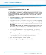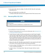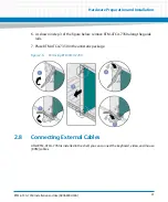
Hardware Preparation and Installation
RTM-ATCA-7350 Installation and Use (6806800H30G)
39
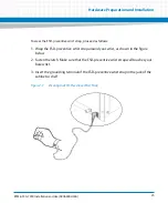
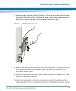
7. Align the upper and lower sides of RTM-ATCA-7350 with the guide rails (the edges
of the slot). Slide RTM-ATCA-7350 along the guide rails until the positioning pins of
RTM-ATCA-7350 are inserted in the positioning holes in the shelf.
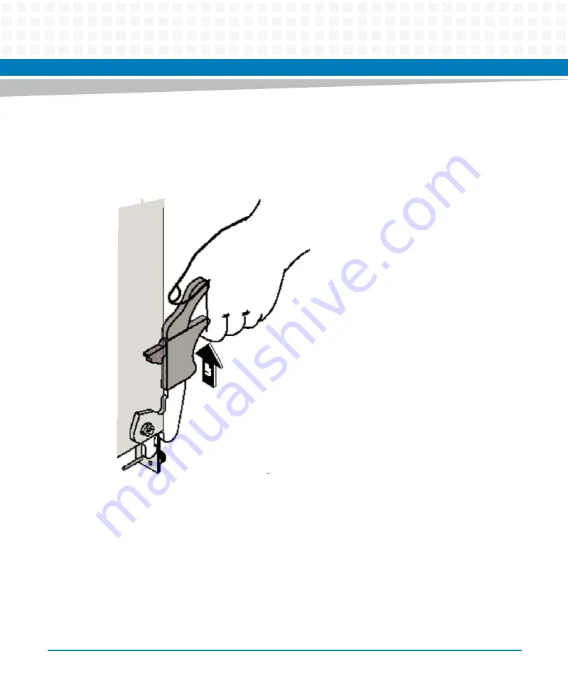
8. Make sure that the ejector handles are fastened to the beam. Close the upper and
lower ejector handles inwards until the inner sides of the ejector handles are
attached to the face plate.
9. Use the screwdriver to fasten the captive screws clockwise to fix RTM-ATCA-7350.
The LEDs of the RTM are off now.
10.Insert the main blade. For instructions on how to install the main blade, refer to
Installing the ATCA-7350 in a Powered Shelf
in
ATCA-7350 Installation and Use
manual.
Figure 2-5
Installing RTM-ATCA-7350
Summary of Contents for RTM-ATCA-7350
Page 1: ...RTM ATCA 7350 Installation and Use P N 6806800H30G September 2014 ...
Page 6: ...RTM ATCA 7350 Installation and Use 6806800H30G 6 List of Tables ...
Page 8: ...RTM ATCA 7350 Installation and Use 6806800H30G 8 List of Figures ...
Page 14: ...RTM ATCA 7350 Installation and Use 6806800H30G About this Manual 14 About this Manual ...
Page 18: ...Introduction RTM ATCA 7350 Installation and Use 6806800H30G 18 ...
Page 46: ...Hardware Preparation and Installation RTM ATCA 7350 Installation and Use 6806800H30G 46 ...
Page 60: ...Controls LEDs and Connectors RTM ATCA 7350 Installation and Use 6806800H30G 60 ...
Page 66: ...Functional Description RTM ATCA 7350 Installation and Use 6806800H30G 66 ...
Page 69: ......

