


Controls, LEDs and Connectors
RTM-ATCA-7350 Installation and Use (6806800H30G
)
56
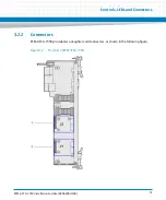
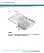
3.3
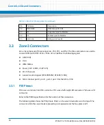
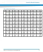
Zone 3 Connectors
Zone 3 is composed of three connectors, P30, P31, and P32. The three connectors are used to
connect RTMs with RTM-ATCA-7350s. Zone 3 defines the following signals:
USB (USB)
VGA
IPMC SMBus
Power (VCC 12VDC, VSBY 5V5)
PCI-E Channels
General control signals (RTM PRESENT, RTM RST, LEDs)
Fabric channel port 0, port 1, port 2, port 3 for the ATCA-7350
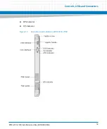
3.3.1
P30 Pinout
P30 uses a common 2mm HM connector. P31 uses a half-height ZD connector. P32 uses a ZD
connector.
Refer to the PICMG specification for the location of the connectors.
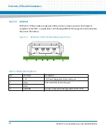
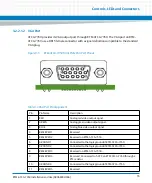
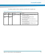
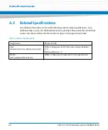
The following table shows the P30 pinout. PinA1 on the server blade side is on the top of the
connector while the server blade is placed top side upwards and the face plate is left.
12
DDC DATA
DDC data pin for CRT.
13
HS
Horizontal sync for Monitor.
14
VS
Vertical sync for Monitor.
15
DDC CLK
DDC pin SCL for CRT.
Table 3-3 VGA Port Pin Assignment (continued)
Pin
Pin Name
Description
Summary of Contents for RTM-ATCA-7350
Page 1: ...RTM ATCA 7350 Installation and Use P N 6806800H30G September 2014 ...
Page 6: ...RTM ATCA 7350 Installation and Use 6806800H30G 6 List of Tables ...
Page 8: ...RTM ATCA 7350 Installation and Use 6806800H30G 8 List of Figures ...
Page 14: ...RTM ATCA 7350 Installation and Use 6806800H30G About this Manual 14 About this Manual ...
Page 18: ...Introduction RTM ATCA 7350 Installation and Use 6806800H30G 18 ...
Page 46: ...Hardware Preparation and Installation RTM ATCA 7350 Installation and Use 6806800H30G 46 ...
Page 60: ...Controls LEDs and Connectors RTM ATCA 7350 Installation and Use 6806800H30G 60 ...
Page 66: ...Functional Description RTM ATCA 7350 Installation and Use 6806800H30G 66 ...
Page 69: ......


