
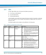
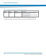
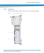


Controls, LEDs and Connectors
RTM-ATCA-7350 Installation and Use (6806800H30G
)
58
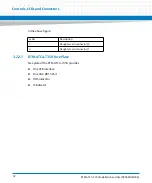
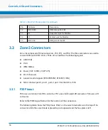
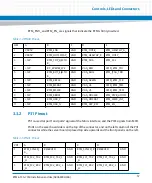
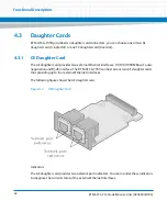
3.3.3
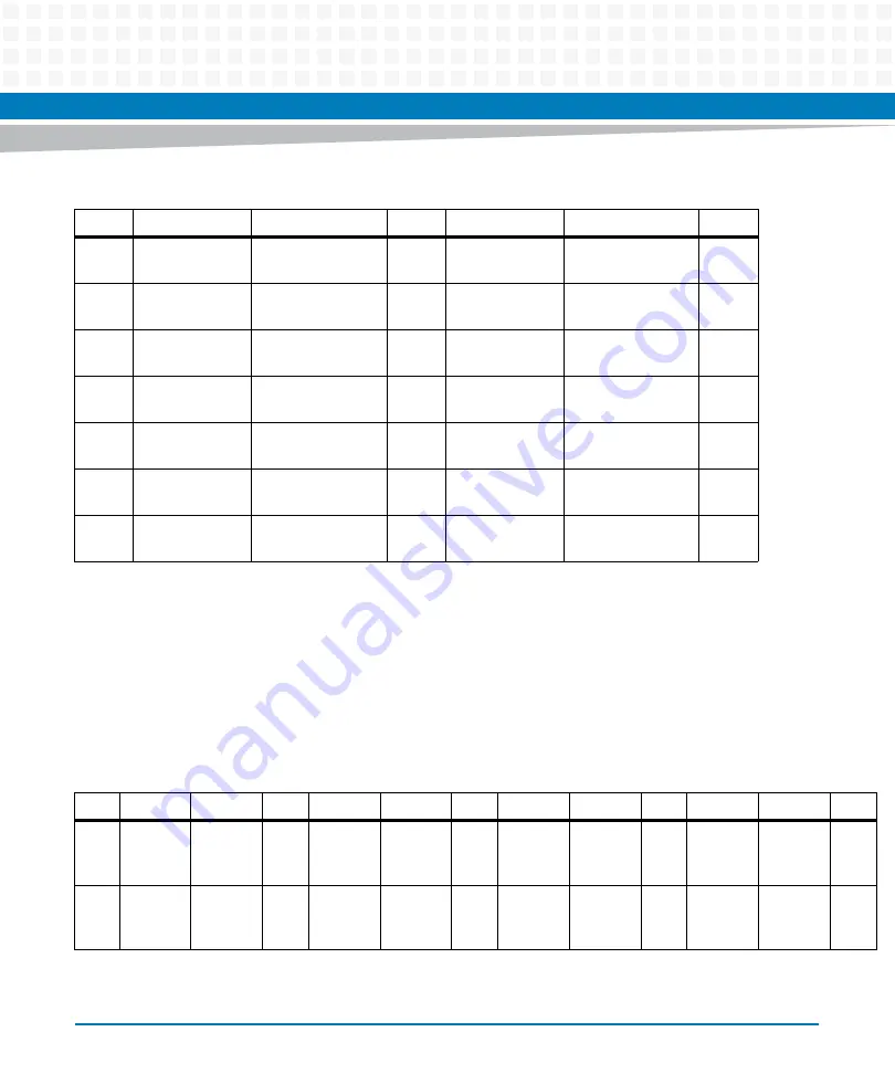
P32 Pinout
P32 is used for port1 and port4 signals of the Fabric interface, and the PCIE signals from front
board.
PinA1 on the server board side is on the top of the connector, and on the left column of the P32
connector while the server board is placed top side upwards and the front panel is on the left.
4
RTM_FC2_TX1
_H
RTM_FC2_TX1_L
GND
RTM_FC1_TX1
_H
RTM_FC1_TX1_L
GND
5
RTM_FC2_RX1
_H
RTM_FC2_RX1_L
GND
RTM_FC1_RX1
_H
RTM_FC1_RX1_L
GND
6
RTM_PE7_PRS
NT_R_
RTM_PE7_RST_
GND
MCH_EXP7_RX
P3
MCH_EXP7_RXN3
GND
7
RTM_EXP7_RX
P3
RTM_EXP7_RXN3
GND
MCH_EXP7_RX
P2
MCH_EXP7_RXN2
GND
8
RTM_EXP7_RX
P2
RTM_EXP7_RXN2
GND
MCH_EXP7_RX
P1
MCH_EXP7_RXN1
GND
9
RTM_EXP7_RX
P1
RTM_EXP7_RXN1
GND
MCH_EXP7_RX
P0
MCH_EXP7_RXN0
GND
10
RTM_EXP7_RX
P0
RTM_EXP7_RXN0
GND
RTM_PCIE7_CL
K_P
RTM_PCIE7_CLK_
N
GND
Table 3-5 PIN 31 Pinout (continued)
ZD1
A
B
C
D
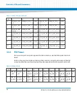
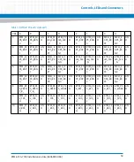
Table 3-6 PIN 32 Pinout
ZD2
A
B
C
D
E
F
G
H
1
RTM_PE
_SDA
RTM_PE
_SCL
GN
D
MCH_E
XP6_RX
P1
MCH_E
XP6_RX
N1
GN
D
RTM_EX
P6_RXP
3
RTM_EX
P6_RXN
3
GN
D
MCH_E
XP6_RX
P3
MCH_E
XP6_RX
N3
GN
D
2
RTM_EX
P6_RXP
1
RTM_EX
P6_RXN
1
GN
D
MCH_E
XP6_RX
P0
MCH_E
XP6_RX
N0
GN
D
RTM_EX
P6_RXP
2
RTM_EX
P6_RXN
2
GN
D
MCH_E
XP6_RX
P2
MCH_E
XP6_RX
N2
GN
D
Summary of Contents for RTM-ATCA-7350
Page 1: ...RTM ATCA 7350 Installation and Use P N 6806800H30G September 2014 ...
Page 6: ...RTM ATCA 7350 Installation and Use 6806800H30G 6 List of Tables ...
Page 8: ...RTM ATCA 7350 Installation and Use 6806800H30G 8 List of Figures ...
Page 14: ...RTM ATCA 7350 Installation and Use 6806800H30G About this Manual 14 About this Manual ...
Page 18: ...Introduction RTM ATCA 7350 Installation and Use 6806800H30G 18 ...
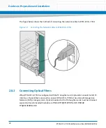
Page 46: ...Hardware Preparation and Installation RTM ATCA 7350 Installation and Use 6806800H30G 46 ...
Page 60: ...Controls LEDs and Connectors RTM ATCA 7350 Installation and Use 6806800H30G 60 ...
Page 66: ...Functional Description RTM ATCA 7350 Installation and Use 6806800H30G 66 ...
Page 69: ......


