Chapter 4
RTM-ATCA-7350 Installation and Use (6806800H30G)
61
Functional Description
4.1
Overview
This chapter describes:
Block diagram
Daughter cards
4.2
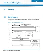
Block Diagram
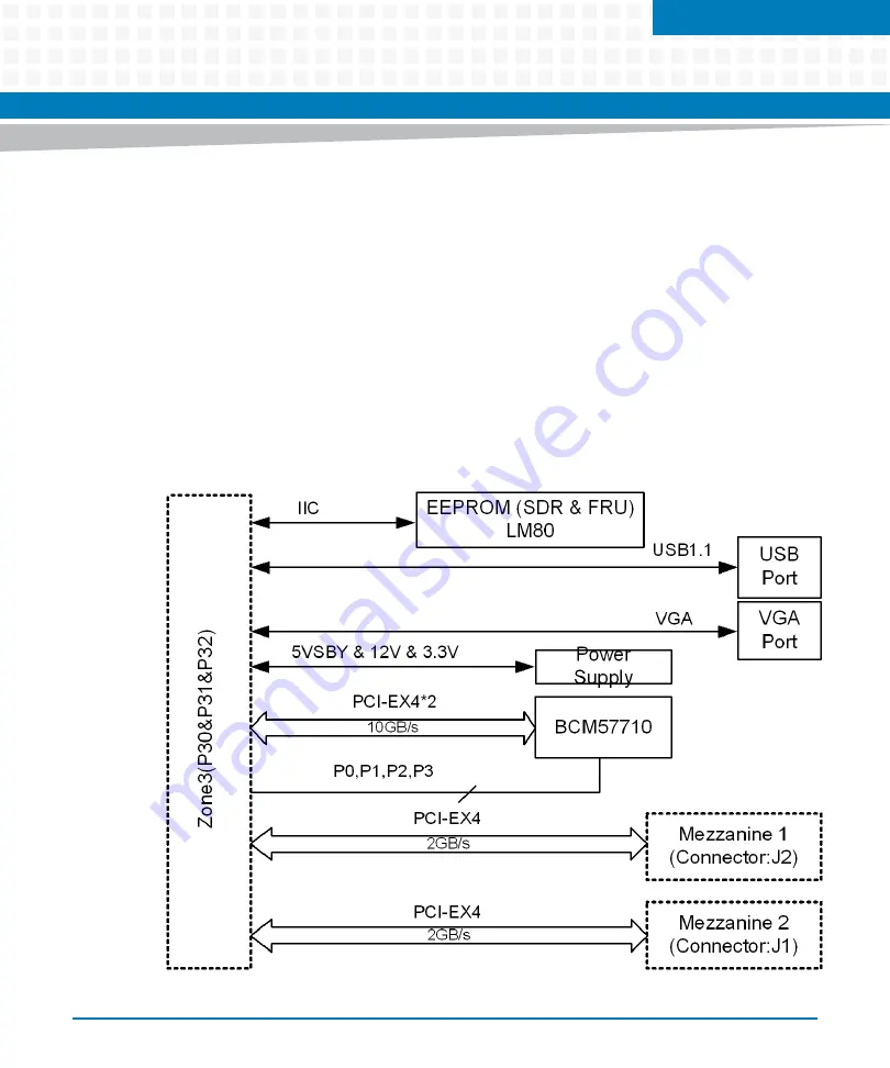
The following block diagram shows the main components of RTM-ATCA-7350 and how they
interact/connect.
Figure 4-1
Block Diagram of RTM-ATCA-7350
Summary of Contents for RTM-ATCA-7350
Page 1: ...RTM ATCA 7350 Installation and Use P N 6806800H30G September 2014 ...
Page 6: ...RTM ATCA 7350 Installation and Use 6806800H30G 6 List of Tables ...
Page 8: ...RTM ATCA 7350 Installation and Use 6806800H30G 8 List of Figures ...
Page 14: ...RTM ATCA 7350 Installation and Use 6806800H30G About this Manual 14 About this Manual ...
Page 18: ...Introduction RTM ATCA 7350 Installation and Use 6806800H30G 18 ...
Page 46: ...Hardware Preparation and Installation RTM ATCA 7350 Installation and Use 6806800H30G 46 ...
Page 60: ...Controls LEDs and Connectors RTM ATCA 7350 Installation and Use 6806800H30G 60 ...
Page 66: ...Functional Description RTM ATCA 7350 Installation and Use 6806800H30G 66 ...
Page 69: ......

