Maps and Registers
ATCA-7360 Installation and Use (6806800J07S
)
162
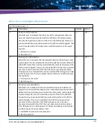
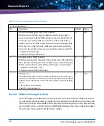
The logical register addresses are shown in the tables below.
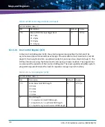
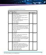
Registers 0x60 (MSB) and 0x61 (LSB) set the Logical Device Base IO for this logical device. For
example for Base IO address 0x3F8 the content of Register 0x60 is 0x03 and the content of
Register 0x61is 0xF8.
0x75
Reserved
0xF0
Reserved
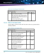
Table 6-18 Logical Device Enable Register
Index Address: 0x30
Bit
Description
Default
Access
0
Logical Device Enable:
0: disabled. Currently selected device is inactive.
1: enabled.The currently selected device is enabled.
1
LPC: r/w
7:1
Reserved
0
LPC: r
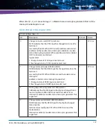
Table 6-19 Logical Device Base IO Address MSB Register
Index Address: 0x60
Bit
Description
Default
Access
7:0
Logical Device Base IO Address MSB
0
LPC: r/w
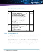
Table 6-20 Logical Device Base IO Address LSB Register
Index Address: 0x61
Bit
Description
Default
Access
2:0
Bits 0 to 2 are read only. Decode is on 8 Byte
boundary.
0
LPC: r
7:3
Logical Device Base IO Address LSB. (Bits 3 to 7)
LPC: r/w
Table 6-17 Logical Device Configuration Register Summary (continued)
Index Address
Description
Summary of Contents for ATCA-7360
Page 1: ...ATCA 7360 Installation and Use P N 6806800J07S May 2016...
Page 26: ...ATCA 7360 Installation and Use 6806800J07S About this Manual 26 About this Manual...
Page 36: ...ATCA 7360 Installation and Use 6806800J07S Sicherheitshinweise 36...
Page 43: ...Introduction ATCA 7360 Installation and Use 6806800J07S 43...
Page 44: ...Introduction ATCA 7360 Installation and Use 6806800J07S 44...
Page 66: ...Installation ATCA 7360 Installation and Use 6806800J07S 66...
Page 258: ...Supported IPMI Commands ATCA 7360 Installation and Use 6806800J07S 258...
Page 284: ...Replacing the Battery ATCA 7360 Installation and Use 6806800J07S 284...
Page 287: ......


