Maps and Registers
ATCA-7360 Installation and Use (6806800J07S)
205
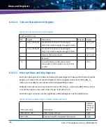
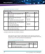
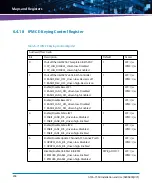
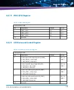
6.4.19 IPMC GPIO Register
6.4.20 LED Status and Control Register
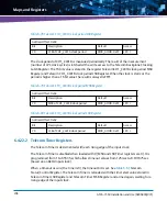
Table 6-72 IPMC GPIO Register
Address Offset: 0x4B
Bit
Description
Default
Access
0
IPMC_GPIO1
Ext.
LPC: r
1
IPMC_GPIO2
Ext.
LPC: r
2
IPMC_GPIO2
Ext.
LPC: r
7:3
Reserved
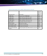
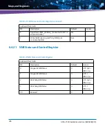
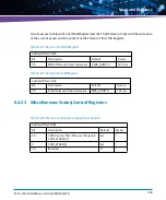
Table 6-73 LED Status and Control Register
Address Offset: 0x50
Bit
Description
Default
Access
0
Control green LED output Signal LED_GREEN_:
0: LED_GREEN_ is driven high.
1: LED_GREEN_ is driven low.
0
LPC: r/w
IPMC: r
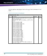
1
Control read LED output Signal LED_RED_:
0: LED_RED_ is driven high.
1: LED_RED_ is driven low.
0
LPC: r/w
IPMC: r
2
Control user LED output Signal LED_USER1_:
0: LED_USER1_ is driven high.
1: LED_USER1 is driven low.
0
LPC: r/w
IPMC: r
3
Control user LED output Signal LED_USER2_:
0: LED_USER2_ is driven high.
1: LED_USER2 is driven low.
0
LPC: r/w
IPMC: r
5:4
Reserved
0
r
Summary of Contents for ATCA-7360
Page 1: ...ATCA 7360 Installation and Use P N 6806800J07S May 2016...
Page 26: ...ATCA 7360 Installation and Use 6806800J07S About this Manual 26 About this Manual...
Page 36: ...ATCA 7360 Installation and Use 6806800J07S Sicherheitshinweise 36...
Page 43: ...Introduction ATCA 7360 Installation and Use 6806800J07S 43...
Page 44: ...Introduction ATCA 7360 Installation and Use 6806800J07S 44...
Page 66: ...Installation ATCA 7360 Installation and Use 6806800J07S 66...
Page 258: ...Supported IPMI Commands ATCA 7360 Installation and Use 6806800J07S 258...
Page 284: ...Replacing the Battery ATCA 7360 Installation and Use 6806800J07S 284...
Page 287: ......

