Controls, Indicators, and Connectors
ATCA-7360 Installation and Use (6806800J07S
)
74
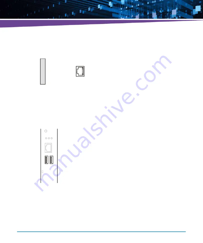
The pinout of the serial interface connector is shown in the following figure.
3.2.3.3
USB Connectors
The blade provides two USB connectors at its faceplate. They are compliant to the USB 2.0
standard and correspond to the blade's USB interfaces 3 and 4. Their location is shown in the
following figure.
Figure 3-8
Serial Interface Connector Pinout
1
8
1
2
3
4
5
6
7
8
n.c.
n.c.
COM1_RS232_TXD
GND
GND
COM1_RS232_RXD
n.c.
n.c.
Figure 3-9
Location of USB Connectors
E
S
E
T
H
/
S
C
O
M
1
USB2
USB1
U1 U2 U3
Summary of Contents for ATCA-7360
Page 1: ...ATCA 7360 Installation and Use P N 6806800J07S May 2016...
Page 26: ...ATCA 7360 Installation and Use 6806800J07S About this Manual 26 About this Manual...
Page 36: ...ATCA 7360 Installation and Use 6806800J07S Sicherheitshinweise 36...
Page 43: ...Introduction ATCA 7360 Installation and Use 6806800J07S 43...
Page 44: ...Introduction ATCA 7360 Installation and Use 6806800J07S 44...
Page 66: ...Installation ATCA 7360 Installation and Use 6806800J07S 66...
Page 258: ...Supported IPMI Commands ATCA 7360 Installation and Use 6806800J07S 258...
Page 284: ...Replacing the Battery ATCA 7360 Installation and Use 6806800J07S 284...
Page 287: ......


