Controls, Indicators, and Connectors
ATCA-7360 Installation and Use (6806800J07S)
75
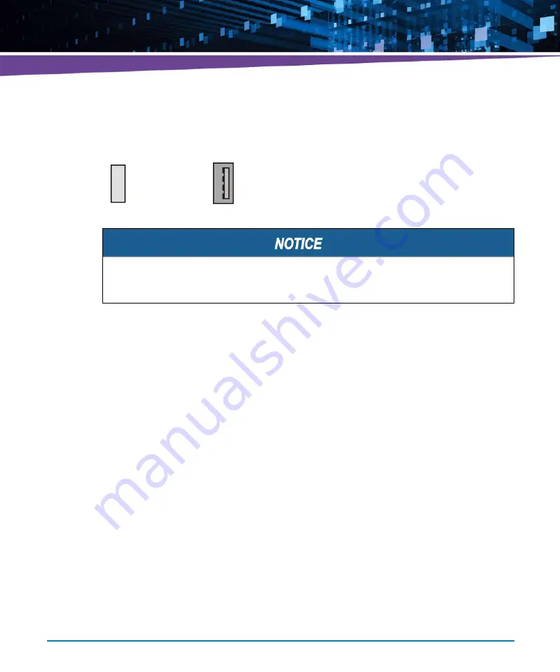
The pinout of each USB connector is given in the following figure.
3.3
On-board Connectors
The blade provides the following on-board connectors:
PMEM/SATA module connector
USB flash module connector
3.3.1
PMEM/SFMEM Module Connector
The PMEM/SFMEM Module connects to the blade through a connector that carries the
following types of signals:
PCI interface signals
I2C signals for connection with on-board IDROM device
Four configuration pins used for memory configuration
One SATA port connection (ICH10 port #5)
Power supply 5V and 3.3V
Figure 3-10 USB Connector Pinout
1
2
3
4
1
4
VP5_USB
USB_x_D-
GND
Exceeding the maximum USB current rating of 500mA per port will result in ATCA-7360
protecting itself through a controlled board shutdown.
Summary of Contents for ATCA-7360
Page 1: ...ATCA 7360 Installation and Use P N 6806800J07S May 2016...
Page 26: ...ATCA 7360 Installation and Use 6806800J07S About this Manual 26 About this Manual...
Page 36: ...ATCA 7360 Installation and Use 6806800J07S Sicherheitshinweise 36...
Page 43: ...Introduction ATCA 7360 Installation and Use 6806800J07S 43...
Page 44: ...Introduction ATCA 7360 Installation and Use 6806800J07S 44...
Page 66: ...Installation ATCA 7360 Installation and Use 6806800J07S 66...
Page 258: ...Supported IPMI Commands ATCA 7360 Installation and Use 6806800J07S 258...
Page 284: ...Replacing the Battery ATCA 7360 Installation and Use 6806800J07S 284...
Page 287: ......


