FRU Installation
AXP640 Installation and Use (6806800M24F
)
144
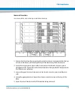
1. Unlatch the lower handle outward by squeezing the lever and the latch together
and turning the handle outward only enough to unlatch the handle from the face
plate, that means until you feel a resistance. Do not rotate the handle fully
outwards.
The blue LED blinks indicating that the shelf manager is informed about the desire
of the blade to power down the payload of both the front blade and the RTM and
the power-down process is ongoing.
2. Wait until the blue LEDs on both the front blade and the RTM are permanently ON.
A permanently switched ON LED indicates that the payload of respective blade or
RTM has been powered down.
3. Unlatch the upper handle and rotate both handles fully outward.
Data Loss
Removing the RTM with the system power on and the blue LED on the front blade still
flashing causes data loss.
Before removing the RTM from a powered system, power down the slot by opening the
lower handle of the front blade and wait until the blue LED is permanently ON.
Summary of Contents for AXP640
Page 1: ...AXP640 Installation and Use P N 6806800M24F May 2014 ...
Page 8: ...AXP640 Installation and Use 6806800M24F Contents 8 Contents Contents ...
Page 10: ...AXP640 Installation and Use 6806800M24F 10 List of Tables ...
Page 50: ...Platform Architecture AXP640 Installation and Use 6806800M24F 50 ...
Page 70: ...AXP640 Shelf Description AXP640 Installation and Use 6806800M24F 70 Figure 2 14 AC Inlet 220V ...
Page 101: ...Site Preparation AXP640 Installation and Use 6806800M24F 101 Figure 3 13 Planning Checklist 2 ...
Page 102: ...Site Preparation AXP640 Installation and Use 6806800M24F 102 ...
Page 112: ...AXP640 Operations AXP640 Installation and Use 6806800M24F 112 ...
Page 136: ...AXP640 Shelf Installation AXP640 Installation and Use 6806800M24F 136 ...
Page 164: ...FRU Installation AXP640 Installation and Use 6806800M24F 164 ...
Page 186: ...Shelf Management Alarm Module AXP640 Installation and Use 6806800M24F 186 ...
Page 189: ......


