Controls, Indicators, and Connectors
SharpSwitch™ PCIE-9205 Installation and Use (6806800U18D
)
54
68
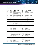
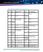
GND
Ground
CPU1_P2E_
EXT_TX_D
_P
PCIe to CPU1 Transmitter
(Diff pair)
69
GND
Ground
CPU1_P2E_
EXT_TX_D
_M
70
CPU1_SA
TA1_RX_
D_P
SATA1 port to CPU1
Receiver (Diff pair)
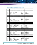
GND
Ground
71
CPU1_SA
TA1_RX_
D_M
GND
Ground
72
GND
Ground
CPU1_SATA
1_TX_D_P
SATA1 port to CPU1
Transmitter (Diff pair)
73
GND
Ground
CPU1_SATA
1_TX_D_M
74
CPU1_SA
TA0_RX_
D_P
SATA0 port to CPU1
Receiver (Diff pair)
GND
Ground
75
CPU1_SA
TA0_RX_
D_M
GND
Ground
76
GND
Ground
CPU1_SATA
0_TX_D_P
SATA0 port to CPU1
Transmitter (Diff pair)
77
GND
Ground
CPU1_SATA
0_TX_D_M
78
RRC
10G_P
RRC_10G_EXT_RX_P
GND
Ground
79
RRC
10G_N
RRC_10G_EXT_RX_N
GND
Ground
80
GND
Ground
RRC 10G_P
RRC_10G_EXT_TX_P
81
GND
Ground
RRC 10G_N
RRC_10G_EXT_TX_N
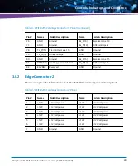
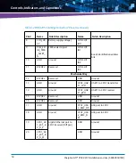
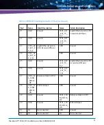
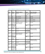
Table 3-2 PCIE-9205 Card Edge Connector 2 Pinout (continued)
Pin #
Name
Side B Description
Name
Side A Description
Summary of Contents for SharpSwitch PCIE-9205
Page 1: ...SharpSwitch PCIE 9205 Installation and Use P N 6806800U18D March 2018 ...
Page 6: ...SharpSwitch PCIE 9205 Installation and Use 6806800U18D 6 Contents ...
Page 8: ...SharpSwitch PCIE 9205 Installation and Use 6806800U18D 8 List of Tables ...
Page 10: ...SharpSwitch PCIE 9205 Installation and Use 6806800U18D 10 List of Figures ...
Page 22: ...SharpSwitch PCIE 9205 Installation and Use 6806800U18D Safety Notes 22 ...
Page 30: ...SharpSwitch PCIE 9205 Installation and Use 6806800U18D Sicherheitshinweise 30 ...
Page 62: ...Controls Indicators and Connectors SharpSwitch PCIE 9205 Installation and Use 6806800U18D 62 ...
Page 68: ...Functional Description SharpSwitch PCIE 9205 Installation and Use 6806800U18D 68 ...
Page 86: ...BIOS SharpSwitch PCIE 9205 Installation and Use 6806800U18D 86 ...
Page 101: ......


