Controls, Indicators, and Connectors
SharpSwitch™ PCIE-9205 Installation and Use (6806800U18D
)
60
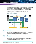
3.3.1
Switch Settings
This section provides switch settings for power up of PCIE-9205 card under MaxCore IPC and
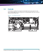
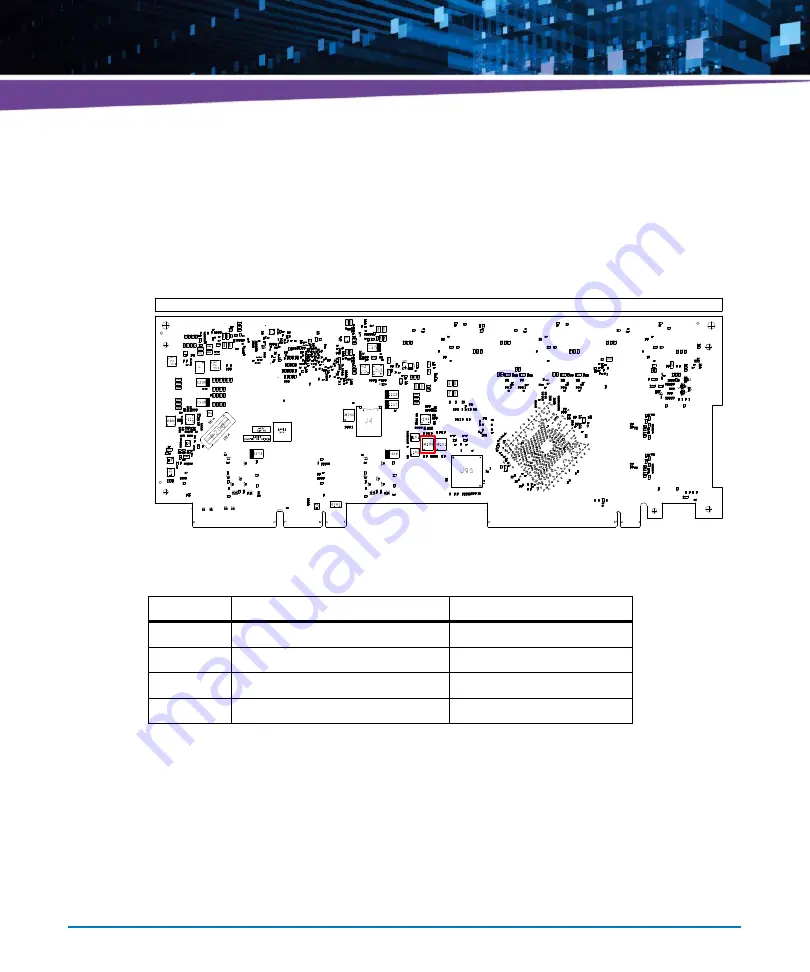
MaxCore Micro systems. The following figure shows SW100 switch location.
Figure 3-6
Location of SW100
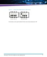
Table 3-6 Switch Settings
Switch
MaxCore IPC (MC1000)
MaxCore Micro (MC1500)
SW100.1
OFF (Down side position)
ON (Up side position)
SW100.2
OFF (Down side position)
OFF (Down side position)
SW100.3
OFF (Down side position)
OFF (Down side position)
SW100.4
OFF (Down side position)
OFF (Down side position)
Summary of Contents for SharpSwitch PCIE-9205
Page 1: ...SharpSwitch PCIE 9205 Installation and Use P N 6806800U18D March 2018 ...
Page 6: ...SharpSwitch PCIE 9205 Installation and Use 6806800U18D 6 Contents ...
Page 8: ...SharpSwitch PCIE 9205 Installation and Use 6806800U18D 8 List of Tables ...
Page 10: ...SharpSwitch PCIE 9205 Installation and Use 6806800U18D 10 List of Figures ...
Page 22: ...SharpSwitch PCIE 9205 Installation and Use 6806800U18D Safety Notes 22 ...
Page 30: ...SharpSwitch PCIE 9205 Installation and Use 6806800U18D Sicherheitshinweise 30 ...
Page 62: ...Controls Indicators and Connectors SharpSwitch PCIE 9205 Installation and Use 6806800U18D 62 ...
Page 68: ...Functional Description SharpSwitch PCIE 9205 Installation and Use 6806800U18D 68 ...
Page 86: ...BIOS SharpSwitch PCIE 9205 Installation and Use 6806800U18D 86 ...
Page 101: ......

