ARTEX PRODUCTS / ACR ELECTRONICS, INC
DESCRIPTION, OPERATION, INSTALLATION AND MAINTENANCE MANUAL
ELT 345 (P/N: A3-06-2880)
Page 29 of 58
25-62-35
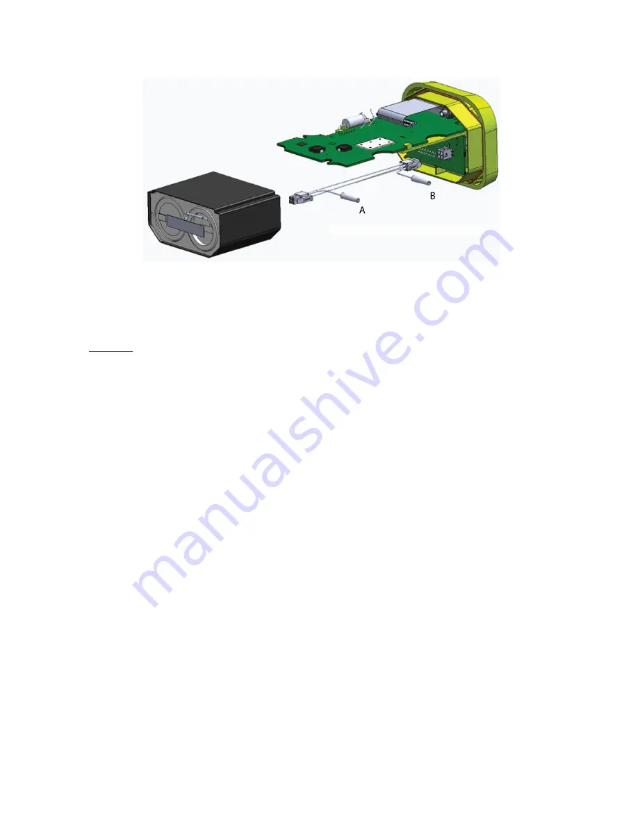
Figure 7 Current Draw Test Setup
4)
Terminate the ELT RF output with a 50 Ω load.
5)
Set the ammeter for the lowest possible scale and connect the leads to A and B.
6)
Measured current must be < 5 µA (micro-amps).
CAUTION:
THE NEXT MEASUREMENT COULD CAUSE THE INTERNAL PROTECTION FUSE OF THE
AMMETER TO BLOW, IF PRECAUTIONS ARE NOT OBSERVED.
7)
Set the ammeter current range to accommodate 4A (amp).
8)
Activate the ELT.
9)
Allow ELT to transmit a 406 MHz burst. This will occur approximately 50 seconds after activation.
10)
Set the ammeter to read approximately 30 mA of current.
11)
Observe reading. Current shall be ≤ 35 mA.
12)
Deactivate the ELT.
13)
Remove the test fixture and reinstall the battery pack in accordance with TASK 25-62-35-450-806 on page 51.
Hints:
a)
Short the meter leads (at the meter) with a banana plug-type jumper lead to protect the fuses in the meter.
b)
Using a spectrum analyzer as a load device, detect when the 406 MHz burst has occurred.
SUBTASK 25-62-35-750-008
M.
Digital Message Verification – Item 5g
1)
Use a beacon reader, such as ARTEX P/N 453-1000, 453-2000, 8700, or 8701 to test the transmitted digital
message.
2)
Connect the beacon tester to the ELT, per the instructions of the reader.
3)
Perform a self-test by placing the control switch in the SELF-TEST position. Once the LED blinks once, release
the switch. Do not hold the switch in SELF-TEST position for longer than 1 second. Example results are shown
in Figure 8 Short & Long 406 MHz Message Examples. Actual messages will vary depending on the protocol and
information programmed into the ELT.
a)
If the ELT is programmed with a location (long message) protocol and disconnected from the aircraft
navigation system or interface device, the message will indicate “Position Invalid” in lieu of position data,
as shown in the right hand example.


