ARTEX PRODUCTS / ACR ELECTRONICS, INC
DESCRIPTION, OPERATION, INSTALLATION AND MAINTENANCE MANUAL
ELT 345 (P/N: A3-06-2880)
Page 43 of 58
25-62-35
3)
Install a ground plane if necessary. Please follow AC 43.13-2B.310 when installing antenna on composite or
fabric covered wood airframes.
4)
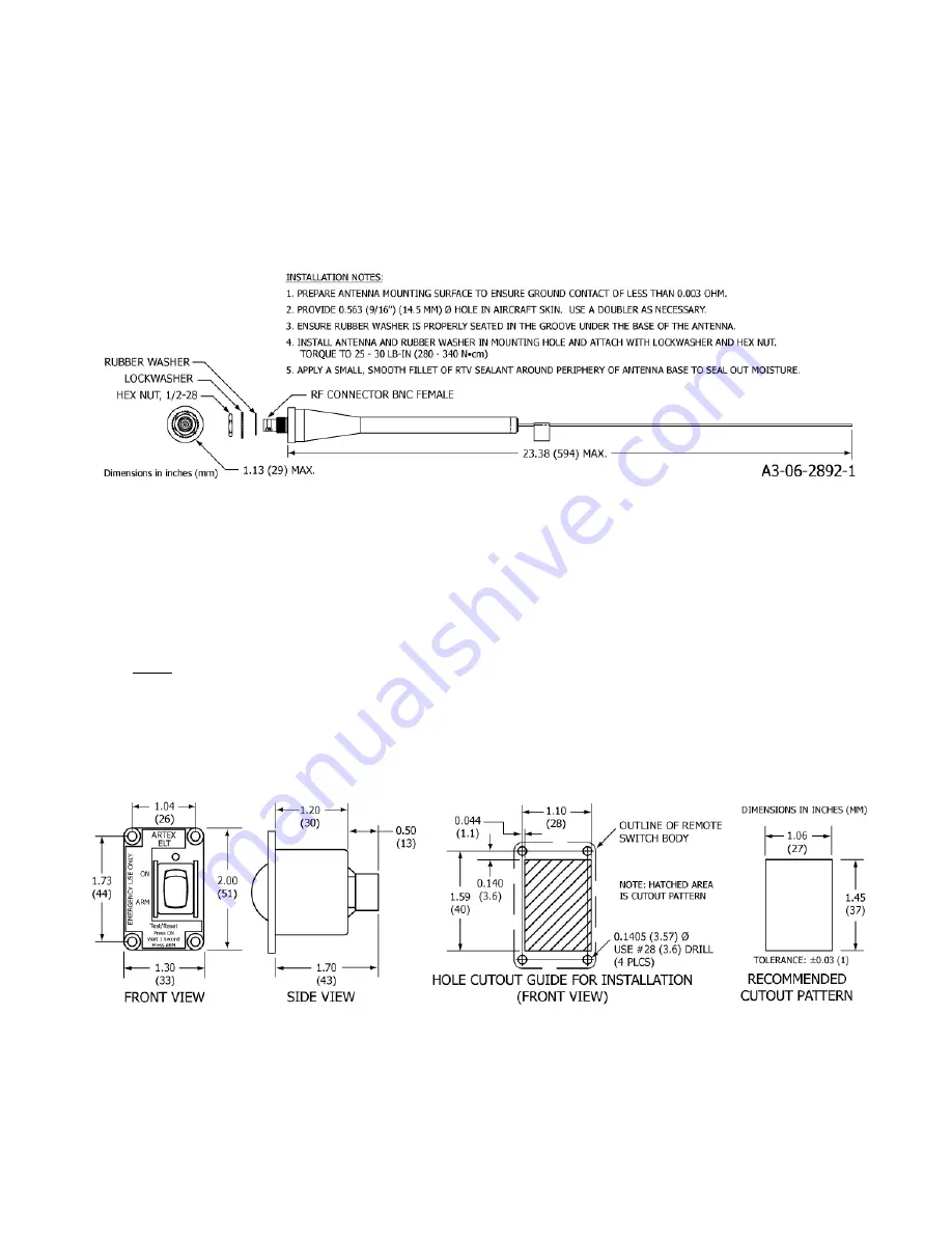
Drill the antenna mounting holes and coax connector hole referring to Figure 14 below.
5)
Mount the antenna referring to Figure 14 below for hardware requirements, torque, and other applicable
installation requirements.
6)
Apply a small fillet of RTV sealant around periphery of antenna base to protect against moisture.
7)
A coax cable is provided as part of some ELT kits.
Figure 14 A3-06-2892-1 Antenna Outlines and Dimensions
TASK 25-62-35-450-803
4.
Remote Switch
SUBTASK 25-62-35-450-001
A.
Location
NOTE:
The ELT 345 must be installed using a 2-wire remote switch, ARTEX P/N A3-06-2757. Note that
the 2-wire remote switch does not require a connection to the aircraft power to operate.
1)
Select a suitable switch location in the cockpit. The switch needs to be visible and accessible, where the pilot
can easily reach the switch and notice the indicator LED.
2)
The switch assembly requires a panel area of approximately 2.0 x 1.3 in. (51 x 33 mm). Figure 15 shows the
dimensions. The clearance behind the panel must allow for the mating connector and harness wires, as well as
the switch depth.
Figure 15 Remote Switch Outline and Dimensions
SUBTASK 25-62-35-450-002
B.
Installation


