background image

Doc.-no.: DPC200-MOD_02_EN

Issue: 08/2019

13

OPERATION

5.7 Threshold  calculation

NOTICE

The device requires a minimum pressure to calculate a volume 
flow.

Minimum pressure = 

0.5 % of the product mesuring range 

PRESSURE < 0.5 % measuring range = 

Display shows 

0 m

3

/h

Minimal flow: 

V_min = √(0.005 x measuring range) x k

Maximal flow: 

V_max = √(measuring range) x k

Exampel: Threshold calculation 

The set limit value must be between minimum and maximum flow. 

As reference device we choose DPC200-MOD with a measuring range of 0...1000 Pa.  
The limit value calculation formula: 

V = √ΔP × k

Given values:  


Measuring range = 

0...1000 Pa

;   k-factor (k) = 

116

;   Limit value (V) = 

1,200 m

3

/h


It follows:  

ΔP= (V / k)

= (1,200 / 116)

2

 = 

107 Pa > 5 Pa = 0.5 % of the measuring range

Minimal flow: 

V_min = √(0.005 x 1000) x 116 = 

259 m

3

/h

Maximal flow: 

V_max = √(1000) x 116 = 

3,668 m

3

/h

Result:  

The limit value of 

1,200 m

3

/h

 is between V_min and V_max and adjustable by 

our 

DPC200-MOD (0...1000 Pa)

5.8 Function description - modbus

Hardware features:

The DPC200-MOD has two connection terminals for the Modbus, which are designated A 
and B. The Modbus line of the DPC200-MOD can be terminated via a further jumper. This 
jumper can be plugged into two positions: terminated or not terminated. The terminating 
resistor is 120 Ohm.

Termination:

A device may only be terminated, if it is at the end of a line. Termination serves to dampen 

reflections of signals and the resulting harmonic oscillations. 

OPERATION

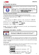
Changes to the holding register are saved to the device’s eeprom.

The durability is 100000 times, and should not be exceeded.

NOTICE

Summary of Contents for DPC200-MOD

Page 1: ...Installation and operation manual DPC200 MOD DIFFERENTIAL PRESSURE VOLUME FLOW CONTROLLER Low pressure sensor with PI control and Modbus RTU digialisation Doc no DPC200 MOD_02_EN Issue 08 2019 ...

Page 2: ...e de www sensor store de 08 2019 DPC200 MOD_02_EN This documentation including all parts is protected by copyright Any utili sation or modification other than permissible under the strict limitations of copyright law is prohibited and liable to prosecution without the approval of the Arthur Grillo GmbH This applies in particular to duplications trans lations microfilming and storage and processing...

Page 3: ...2 Wall mounting 4 Start up 4 1 Overview DPC200 MOD 4 2 Schematic view inside 4 3 Pressure connections 4 4 Electrical connection 4 5 Zero adjustment 5 Operation 5 1 Start menu 5 2 Menu structure 5 3 Start up modbus control 5 4 Measuring mode 5 5 Control mode 5 6 Adjustable parameters 5 7 Threshold calculation 5 8 Modbus RTU 6 Maintenance 7 Warranty 8 Troubleshooting 9 Disposal 10 Specifications 10 ...

Page 4: ...erial damage or minor or moderate bodily injuries CAUTION 1 2 Used pictograms and symbols In this manual the following symbols are used General hazard symbol dan ger warning caution Signal word for important information regarding the product which needs to be specifically pointed out NOTICE Hazard word Type of hazard Hazard source Hazard prevention 1 3 General notes This manual contains informatio...

Page 5: ...or as a manipulated variable of the closed loop controller 2 3 Functional description A diaphragm measuring system is used as sensor element This system consists of a thin diaphragm a spring adapted to the measuring range and the pressure chamber of the housing Combined with a differential transformer it results in a precise robust and dura ble measurement method The evaluation takes place in the ...

Page 6: ...aterial damage Read the manual carefully before installation and operation Only experienced stuff may connect the device and bring it into operation CAUTION 3 1 Dimensions All dimensions in mm ø6 ø5 M16x1 5 4 5 104 54 95 70 The device is position depended The DPC200 MOD must be mounted vertically NOTICE 3 2 Wall mounting 1 Hold the DPC200 MOD against the wall Mark the mounting holes 2 Drill mounti...

Page 7: ...er 2 Cable gland 3 Pressure connection 1 4 Pressure connection 2 5 Cable gland 1 2 3 4 5 4 2 Schematic view inside Button B1 and B2 serve for the operation of the menu 4 3 Pressure connections Connect all pressure connections properly with plastic tubing inner diameter 5 or 6 mm Button 1 Button 2 ...

Page 8: ... magnet Do not use buttons B1 or B2 Adjustment Remove the tubing from the pressure connections Hold the bar magnet N S as shown here to the zero point adjustment for a short period of time to activate an internal reed switch The new zero point will be displayed and stored 5 Operation 5 1 Start menu For operating the menu unscrew the front cover to reach buttons B1 and B2 N S 5 6 B MODBUS A 15 30 V...

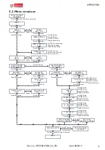
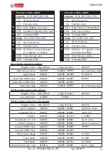
Page 9: ...p parameter 50 i parameter 3 15 controling mode positive heating controling negative cooling back and confirm Press B1 button to leave menu P control mode P 150 Pa unit metric fan k factor k 70 Press B1 Reset Press B2 Select Press B1 Confirm Display flashes once Press B1 button menu Press B2 button Press B1 button Press B2 button Press B2 button Press B2 button Press B2 button Press B2 button Pres...

Page 10: ...tch between diff pressure volume flow Press button B2 to get to the next menu item 5 3 Start up modbus control Display Action controlling mode ΔP 150 Pa Start menu Press button B1 approx two seconds menu Press button B2 to get to the next menu item modbus Press button B1 to switch between on off Press button B2 to get to the next menu item If selected parameter volume flow fan k factor k 70 Button...

Page 11: ...button B2 to get to the next menu item controlling mode positive heating Press button B1 to switch between positive heating negative cooling Press button B2 to go to the next menu back and confirm Press button B1 to leave the menu Press button B2 to stay in the menu Display Action controlling mode ΔP 150 Pa Start menu Press button B1 approx two seconds menu Press button B2 to get to the next menu ...

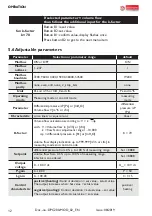
Page 12: ...ential pressure in Pa or InH2 O volume flow display indication up to 999 999 m3 h or cfm in measuring mode and control mode K 70 Setpoint differential pressure from 0 p to 100 of measuring range Set 8888 volume flow from 0 5 up to 100 of measuiring range k factor is considered Set 8888 Output voltage 0 10 0V dc Uout 10V dc P gain 0 1 000 P 50 I gain 0 100 00 I 3 15 Control characteristic positive ...

Page 13: ... 107 Pa 5 Pa 0 5 of the measuring range Minimal flow V_min 0 005 x 1000 x 116 259 m3 h Maximal flow V_max 1000 x 116 3 668 m3 h Result The limit value of 1 200 m3 h is betweenV_min andV_max and adjustable by our DPC200 MOD 0 1000 Pa 5 8 Function description modbus Hardware features The DPC200 MOD has two connection terminals for the Modbus which are designatedA and B The Modbus line of the DPC200 ...

Page 14: ...ad of the parity bit another stop bit is sent This mode is suitable for heavily disturbed connections Telegram structure A send telegram always consists of two bytes and three words 8bit 8bit 8bit 8bit 8bit 8bit 8bit 8bit ID FC DA DA D D CRC CRC 8bit 8bit 16bit 16bit 16bit The telegram is transmitted byte wise only in the Modbus context some bytes are regarded as words Function code The device sup...

Page 15: ...lues decimal metric imperial 0x00C0 0x0000 0x0001 metric 0 imp 1 measurand ΔP V 0x00C1 0x0000 0x0001 ΔP 0 V 1 K factor 0x00C2 0x0000 0x2710 1 10000 characteristic lin rad 0x00C3 0x0000 0x0001 lin 0 rad 1 control meassure 0x00C4 0x0000 0x0001 ctrl 0 measure 1 set point HIGH share 0x00C5 0x0000 0x000F 999999 set point LOW share 0x00C6 0x0000 0x423F Max output voltage 0x00C7 0x0000 0x0064 0 10 0V P p...

Page 16: ...o the device beyond the intended use Disasters due to external influences and force majeure 8 Troubleshooting Description Activity Display does not show anything Check electrical connection Measurement stays zero Function test with a slight pressure increase in measu ring mode for differential pressure Measuring error Perform zeroing as described in chapter 4 5 Error remains Contact manufacturer A...

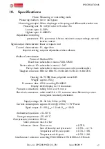
Page 17: ...ential transformer Pa inH2 O oder m3 h oder cfm 0 50 Pa 0 6000 Pa P I parameter k factor maximum output voltage normal inverse control linear or square root PI algorithm setpoint adjustable within software Modbus RTU selectable in menu 7200 57600 selectable in menu 1 247 selectable in menu none even odd none2stopbits 8 Bit ID 8 Bit FC 16 Bit DA 16 Bit D 16 Bit CRC UL 94 HB Case polyamid cover ABS ...

Page 18: ...06 03 correction 1 2011 06 Electromagnetic compatibility EMC Part 6 2 Generic standards Immunity for industrial environments DIN EN 61000 6 3 2011 09 Electromagnetic compatibility EMC Part 6 3 Generic standards Emission standard for residential commer cial and light industrial environments You can order the Declaration of Conformity at Arthur Grillo GmbH Am Sandbach 7 40878 Ratingen Phone 0 21 02 ...

Reviews: