background image

11

MOUNTING INSTRUCTIONS

Information

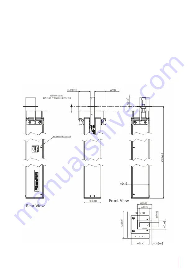
Cut a hole in the table surface where the DynamicCableRetract top 
surface will be installed

.

Ensure that there is enough space under the table to install the 
DynamicCableRetract. 
The output of the cable and connections of the device are in the 
back side (As shown in the picture).
 

Summary of Contents for DynamicCableRetract AHDCRHDMI

Page 1: ...DynamicCableRetract AHDCRHDMI HDMI motorised cable retraction system User Guide Danish craftmanship Mediterranean soul Technology Serving Desing ...

Page 2: ......

Page 3: ...NTENTS EC REGULATIONS AND SECURITY 6 SAFETY INSTRUCTIONS 6 SYSTEM DESCRIPTION 8 MOUNTING INSTRUCTIONS 10 INPUT CONNECTORS 18 AHLINK 19 AHNET PROTOCOL 22 INFORMATION ON DISPOSAL 25 WARRANTY TERMS AND CONDITIONS 26 ...

Page 4: ... integration and for a maximum reliability Please read this installation and operating instructions carefully and keep them in a safe place for future reference We remain at your entire disposal if you have any suggestions that would help us improve our products Henrik Holm General Manager hholm albiral com ...

Page 5: ... based on quality materials and the latest technology Products which endow meeting and conference rooms with silent ergonomic innovative and aesthetic solutions that integrate into the furniture hang from the walls as works of art or are used as interactive points of information The world of Arthur Holm Arthur Holm offers a selection of unique elegant versatile flexible and ergonomic products that...

Page 6: ...ximum allowed by the cable used Do not place anything on the power cord Do not locate this product where a person may walk or trip over the cord EC REGULATIONS AND SECURITY ATTENTION Do not disassemble or modify the device in any way This symbol warns of the presence of dangerous un insulated voltages inside some of the components of sufficient magnitude to expose people to risk of electronic shoc...

Page 7: ... the equipment to Rain or water Excessive heat cold or humidity Area exposed to direct sunlight Dirty areas Equipment generating strong magnetic fields Avoid placing open containers of liquid near the equipment Keep a minimum distance of 30 mm in order to have good ventilation Never place above the device any sources of flames such as lighted candles etc If you are using the device in extreme weat...

Page 8: ...ence will not occur in a particular installation If this equipment does cause harmful interference to radio or television re ception which can be determined by turning the equipment off and on the user is encouraged to try to correct the interference by one or more of the following measures Reorient or relocate the receiving antenna Increase the separation between the equipment and receiver Connec...

Page 9: ...ns Top plate 20 x 44 mm Housing below the table 80 x 674 x 84 mm Weight 3 75Kg Control Capacitive sensor AHNet RS422 I O AHLink Cable type HDMI Cable length 600 mm Cable length below table 700 mm Power consumption 15W Warranty 2 years Box Contents Before the installation of your retractable cable please check the contents of the shipping box it must contain the following items AHDCRHDMI unit Power...

Page 10: ...nents can cause danger and should be avoided by all mean Not complying with these direction will result in a loss of the Arthur Holm warranty Albiral Display Solution S L shall not be held liable for any loss or injury incurred as a result of modifications made to goods by anyone other than the supplier or the supplier s authorised representative without the supplier s written permission Such modi...

Page 11: ...table surface where the DynamicCableRetract top surface will be installed Ensure that there is enough space under the table to install the DynamicCableRetract The output of the cable and connections of the device are in the back side As shown in the picture ...

Page 12: ... table can not be made with precision a cover plate is supplied in order to hide the cut imperfections DynamicCableRetract can be installed in tables with a thickness from 10mm 0 39 to 50mm 1 97 For thickness over 50 mm it will be necessary to mill the lower part of the table ...

Page 13: ...in the table bracket as indicated below Mounting Jig 3 From below the table place the mounting jig with the raised square into the already made cut out make sure the mounting jig is centered in the cut out 4 Align the bracket with your table axis and mark the screws position Remove the mounting jig from the table bracket Mount the table bracket ...

Page 14: ...ng table brackets Place the brackets as shown in the drawing and tighten them down using the nuts M4 Place the vertical adjustment screws 2 2 into the bracket so that the tip of the screw is flushed with the upper side of the bracket ...

Page 15: ...Tighten each nut gradually until the DynamicCableRetract top plate surface is flush with of the table surface or cover plate For the standard installation flush the top plate surface with the top surface of the table For the installation with cover plate place the cover plate over the table surface and flush the top plate with the top Surface of the cover plate Do not stick the cover plate at this...

Page 16: ...screws gradually There is a M6 screw in every corner tighten one more than others you can level the DynamicCableRetract top surface of the table or cover plate 4 Tighten x4 M6 screws to block the device Before blocking The DynamicCableRetract top surface must be centered in the hole ensuring that the perimeter has the same separation on all ...

Page 17: ...if it cannot be made properly Follow next steps to stick the cover plate to top surface 1 Clean the table Surface where the cover plate is goning to be taped 2 Remove the adhesive protection from the back of the cover plate 3 Place the cover plate centered with respect to the DynamicCableRetract top plate ensuring that the perimeter has the same separation on all 4 sides ...

Page 18: ...gnal RS422 output Up to 30 devices can be connected on the same RS422 bus Termination Activate ON the termination ONLY on the last unit of the RS422 bus Address AHnet address for the addressable AHnet command protocol Address 00 is reserved for service 12V D C Power supply input connector Service Used for firmware upgrade ...

Page 19: ...cally deactivate the AHlink signal if there is no device mobile or tablet connected for more than 2 minutes To control and set up the unit using AHlink download AHlink App from the App Store IOS system or from Google Play Android system The App is free Execute the AHlink App on your mobile phone On the AHlink App options it is recommended not to select Auto Connect and select Portrait on Orientati...

Page 20: ...nk name always begins with AH characters and the fourth last MAC AHlink address Select the device to control and set up the unit When selecting the device the first page will upload on the mobile phone This page is used to check the device and for basic diagnostic during the installation process ...

Page 21: ...2 port INFORMATION OF THE SENSOR STATUS S1 Activate when the HDMI cable is inside S2 Active when the cable cover trap is open S3 Deactivated when the cable is at the maximum outside position indicates the screen is completely opened AHNET ADDRESS Configuration of the AHnet address of the unit password PASSWORD Password needed to access the technical configuration page ...

Page 22: ...ata RX 4 NC 5 NC 6 Data RX 7 NC 8 NC Connection PINS 1 2 The units respond PINS 3 6 The units receive instructions Protocol to control the unit by addressable RS422 bus You can connect up to 30 monitors on the same RS422 bus You can use a AH Interface Ethernet to control the RS422 bus The units should have a set address and the address must start by 1 Maximum cable length between ends 500 m 1640 f...

Page 23: ...SCRIPTION RESPONSE FA XX 08 01 00 GO UP FB XX 08 01 00 FA XX 08 00 00 GO DOWN FB XX 08 00 00 FA XX 08 05 00 BUTTON LOCK FB XX 08 05 00 FA XX 08 04 00 BUTTON UNLOCK FB XX 08 04 00 FA XX 14 00 00 INQUIRY CONTROL BYTE FB XX 14 CB1 CB2 XX Number of the DynamicTalk address Up to 30 devices for each RS422 BUS CB1 Response in 8 bits of the monitor status CB2 Not implemented ...

Page 24: ...OSITION 1 DOWN POSITION 2 3 BUTTON LOCKED 1 4 5 6 7 FAILURE IN THE SYSTEM 1 To send an order to all the devices you must use the address F6 Hex Byte1 In this case the units do not send a reply Use shielded FTP RJ45 cables for RS422 BUS ...

Page 25: ...ll help save valuable resources and prevent any potential negative effects on human health and the environment which could otherwise arise from inappropriate waste handling Please contact your local authority for further details of your nearest designated collection point Penalties may be applicable for incorrect disposal of this waste in accordance with national legislation For business users in ...

Page 26: ...aid by Albiral Display Solutions Although Albiral Display Solutions S L pays for freight and insurance costs Albiral Displays Solutions will not be responsible for any damages caused by the transportation of the goods if the customer does not inform in writing when receiving the goods 3 2 After 30 days of the purchase date the beneficiary of the warranty will pay both freight and insurance costs A...

Page 27: ...ransportation 8 The warranty is not valid if the beneficiary of the warranty does not include a RMA form and a copy of the purchasing invoice Please note that laws vary from country to country and the same provisions of this warranty may not apply to you If you have any doubts concerning the terms of this warranty please contact business albiral com 34 938 502 376 Copyright Dec 2020 All rights res...

Page 28: ......

Page 29: ... Sant Hipòlit de Voltregà 08512 Barcelona Spain tel 34 93 850 23 76 23 83 fax 34 93 850 25 50 23 72 web www arthurholm com e mail marketing arthurholm com This manual can be modified without previous notice ENG June 2020 P27178ITEP P27178RUPC P27178USPC P27284DEEP P27284EPPC P27284ESEP P27284GBEP P27284RUPC P27284USPC P27715ESEP P28089DEEP P28089ESEP P28089ITEP P28089USPC P28090EP00 P31160ESES P31...

Reviews: