background image

Aport-211S User Guide 

5


2.7  Serial Port Pin Assignments 

Serial Port COM1 uses a Male DB9 connector and it includes RS-232, RS-422 and RS-485 signal 

and pin assignments are described as follow: 


Pin No. 

Transmission Signals 

RS-232 

4-wire RS-485 

RS-485 

DCD 

TxD- 

RxD 

TxD+ 

TxD 

RxD+ 

Data+ 

DTR 

RxD- 

Data- 

GND 

GND 

GND 

DSR 

RTS 

CTS 


2.8  Digital I/O 

Digital I/O uses DB9 connector and the pin assignments are described as follow: 


Pin 1: 

DIO0 


Pin 2: 

DIO1 


Pin 3: 

DIO2 


Pin 4: 

DIO3 


Pin 5: 

DIO4 


Pin 6: 

DIO5 


Pin 7: 

DIO6 


Pin 8:

 DIO7 


Pin 9: 

GND 


DIO0 to DIO5 are TTL compatible Programmable DIO and DIO 6 to DIO7 are CMOS compatible 

Programmable DIO.    All the DIO channel are pull up +5VDC with a 4.7K Ohm resistor. 


Summary of Contents for Aport-211S

Page 1: ...Aport 211S Single Port Serial to Ethernet Gateway User Guide Version 1 0 Copyright Artila Electronics Co Ltd All Rights Reserved...

Page 2: ......

Page 3: ...7 Serial Port Pin Assignments 5 2 8 Digital I O 5 2 9 Factory Default Settings 6 2 10 Configure Aport 211 6 3 Java Configuration 7 3 1 Install Java Configuration Utility 7 3 2 Serial and Data Packing...

Page 4: ...5 3 Telnet Console Mode 13 5 4 Forgot Password 14 5 5 Command Syntax 14 5 6 Echo Syntax 17 6 Appendix A 18...

Page 5: ...232 RxD TxD RTS CTS DSR DTR DCD GND RS 422 RX RX TX TX GND RS 485 Data Data GND Baud Rate 300 38400 bps Parity None Even Odd Data Bits 7 8 Stop Bits 1 2 Flow Control RTS CTS XON XOFF Protection 15KV E...

Page 6: ...Aport 211S User Guide 2 1 3 Optional Accessory DK 35A 36 DK35A 000 DIN RAIL Mounting Kit PWR 12V 1A 31 62100 000 110 240VAC to 12VDC 1A Power Adaptor...

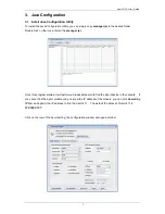
Page 7: ...rnet Port Connect a RJ45 Ethernet cable to the Ethernet port of Aport 211 The Link Activity light will keep solid yellow color if Ethernet cable is corrected to the network and this light will keep fl...

Page 8: ...pressing RESET button 2 6 LED Status The LED provides the Aport 211 operation information The LED status is described as follow Power LED Power LED keeps ON if power 9VDC to 40VDC is correctly input t...

Page 9: ...5 1 DCD TxD 2 RxD TxD 3 TxD RxD Data 4 DTR RxD Data 5 GND GND GND 6 DSR 7 RTS 8 CTS 9 2 8 Digital I O Digital I O uses DB9 connector and the pin assignments are described as follow Pin 1 DIO0 Pin 2 DI...

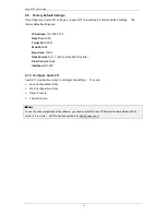
Page 10: ...ud rate 19200 Data Format N 8 1 Parity Data bits Stop bits Flow Control None Interface RS 232 2 10 Configure Aport 211 Aport 211 provides four ways to configure the settings They are Java Configuratio...

Page 11: ...t the manager jar Once this program started it will perform a broadcast search to find the Aport device in the network If you cannot find the Aport module and you know the IP address of the module you...

Page 12: ...The Delimiters are maximum two bytes Hex format ASCII code If you use Carriage Return CR and Line Feed LF as delimiters you can specify 0D0A or 0d0a 3 3 TCP IP Network Settings The group of TCP IP Ne...

Page 13: ...ed access Password Settings Enter the new password will enable the password authentication Password is required to login Java Configuration and Web configuration Pages in the next entry 3 6 Save Confi...

Page 14: ...file will pop out as follow The configuration is a text file and uses extension of txt If you use Text editor to open the configuration command you will notice that the configuration file contains th...

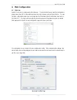
Page 15: ...ply type the IP address to the Web Address input such as 192 168 2 127 The Login windows will ask you enter password if the password option is enabled After password confirmed the web configuration pa...

Page 16: ...ng the Convert button and you can find a binary file fsdata anf has been created Use this binary file to upload to Web server You can see the converted file is available in the Upload binary file to d...

Page 17: ...port setting you can use SW1 to reset it to factory default setting as use following setting Baud rate 19200 Data Format N 8 1 Parity Data bits Stop bits Flow Control None Interface RS 232 Now you ca...

Page 18: ...d syntax is Delimiter Command Carriage Return CR Line Feed LF Delimiter one byte The command begins with a delimiter of dollar sign and if Aport 211 receives the correct command it will response with...

Page 19: ...TC TCP Client G S OC TCP connection timeout option AC always connect TO Disconnect if timeout G S OU Timeout clock 0 65535 unit ms e g SOU500 G S OD Data Packing Three parameters 0 Delimiter Option 1...

Page 20: ...3 6 7 set DIO1 DIO2 DIO3 DIO6 DIO7 as output G DM Get Digital I O mode e g GDM the response is GDM I O O O I I O O S DOH Set DO channel High Output e g SDOH 1 3 7 S DOL Set DO channel Low Output e g...

Page 21: ...n string Status OK or FAIL For example Set the IP Address by sending command SLI192 168 2 125 CR LF Echo string SLIOK CR LF means the new IP address is successfully transferred to the module and the n...

Page 22: ...count can be made variable if required Note this is optimised for 32 bit CPUs with fast shift capabilities It can very easily be ported to assembly language on most CPUs delta is chosen to be the real...

Page 23: ...y z 4 z 5 z sum k sum 3 w 0 y w 1 z 2 The TEA H ifndef __XTEA_H__ define __XTEA_H__ void encipher unsigned long const v unsigned long const w const unsigned long const k void decipher unsigned long co...

Reviews: